BrewPi Dual Valve Controller

I am answering a question in another thread, but thought this might spark some more discussion so a separate thread would be better.

I have made a dual valve controller to control motorized ball valves via OneWire.
With this board, many ball valves can be connected directly to the BrewPi Spark. They are controlled and powered via the RJ12 ports.

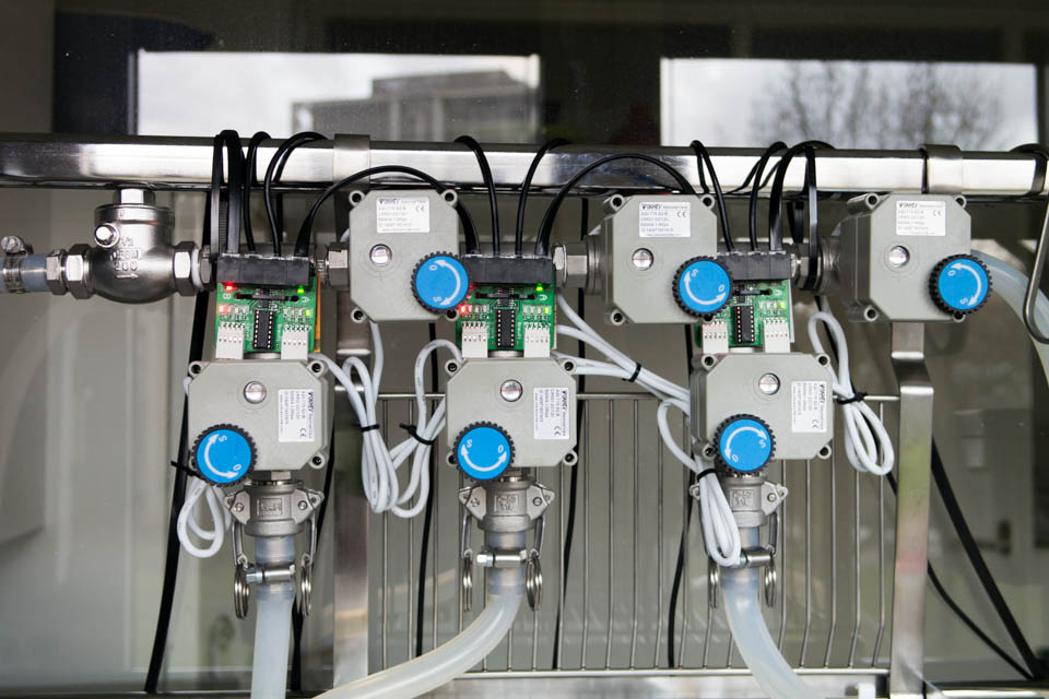
I designed the boards to make wiring everything a lot easier. I have 12 valves in my setup and I don’t want to run a wire to each one from the control panel. In the bottom photo, the leftmost wire is from the control panel and all the wires that go over the rail are temperature sensors.

The valve controller is built from a OneWire 8 channel switch (DS2408) and a dual H-bridge (SN754410, L392D equivalent).
The OneWire switch drives the dual H-bridge with 4 pins and can read the feedback switches inside the valves with the other 4 pins.

Each valve has 4 status LED’s: open, closed, opening, closing. The opening and closing LEDs are parallel to the motor, the open/closed LEDs are switched by the feedback switches inside the valve.

This board is designed for CR-501 valves:

These valves have 2 feedback switches and can be actively closed and opened. The motor automatically stops when they are fully open or closed, but it can also be stopped in between. With the feedback signals, BrewPi could measure how much time it takes to go from fully open to fully closed and could potentially stop in between as well.

The boards and valves can be powered from the RJ12 bus on the BrewPi Spark, they require little current. This makes wiring very easy: they can be daisy chained and each board will have 2 places free for extra temperature sensors (see first photo).

The board could also be used for 30x valves, by driving the H-bridge with 11/10 or 00/01 instead of 10/01. You will not have the feedback signals and cannot open the valve half-way. This is the downside of the 30x valves and the reason I picked 501.

Here is the schematic of the board:

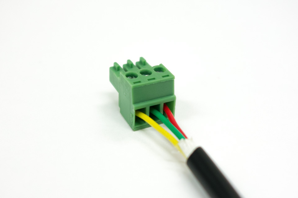
So far I only made 15 prototype boards, but I plan to start selling these board and CR-501 valves in about a month. I will sell the valves with connectors already assembled, you only have to plug them into the controller board.

One issue that I still have not figured out is how to make the enclosure for these. These boards would benefit form a waterproof enclosure, being close to valves/fittings etc. Entirely waterproof is not possible, because the connectors are not waterproof, but at least it should be protected from splashing water.

How can I make a waterproof enclosure, but keep the status LEDs visible?
One option would be to use a transparent plate on top. I have not figured out a better alternative yet.

How can these boards be attached to the valves?
Maybe a good idea would be to assemble PCB and enclosure with one or 2 pipe clamps like this:

Another thing to keep in mind is that the enclosure should be able to handle 100C temperatures.

Any feedback and ideas are very welcome!

1 Like

Elco,

This is very nice looking and cant wait to get ahold of some. For the enclosures, I would think you could doing something like the spark enclosures minus the screen hole. Something that is discrete. do you have to have one board for each or could you have a board that houses all connections. with a wire running to each valve? I would think for this you can keep it away from the fittings and the heat that comes with that. Not sure just thinking of ideas.

the pipe clamp could be screwed into the back of the board housing from the screw terminal shown in the picture. This would keep the board off the hot pipe itself. The case could be black with a very small strip of clear plastic on top to show LEDs or you could keep it open to allow for heat to vent/ if any.

Thanks for input on the control of 30x valves. If I understand this correctly then 1 board should be able to control 4 valves if I pull 12V from another one of the extra RJ12 connectors. My valves are currently hooked up to a small switch box with 3 way switches and the interface board will end up inside the box. This allows me to control the valves manually or automatically.

1 Like

You can use LED light pipes to keep the LEDs visible as well.
I think some type of stud out the back of the case, or tapped inserts to screw into to allow flexibility would be ideal. You could then use the pipe clamps or other mounting options.
If you put the connectors in the case, maybe a clam shell and use pass throughs it may be more water resistant.

1 Like

This is a quick rendition of what I was thinking. By having the cables come out 90 degrees of where the connections are it will be very splash proof. The lid could be screwed onto the box with the LED Pipes epoxied into the lid. The lid would be recessed along the edge to to fit “inside” the box with the very outer edges flush on the box walls.
LED Light pipe link for example:
http://www.mouser.com/ProductDetail/Bivar/PLP2-215/?qs=sGAEpiMZZMuu2qEGwSNRoHT8YVepB4iW9x8KbnpUATQ%3D
This would be a cost effective way of making a splash proof enclosure.

I use items like this:
http://www.amazon.com/Water-Proof-Plastic-Glands-Fasteners/dp/B00EZ9V6SC/ref=sr_1_2?ie=UTF8&qid=1421249047&sr=8-2&keywords=black+cable+gland+water

To water proof my cables into an enclosure, but I am fortunate enough to have the tools required to make my own cables with rj connectors.

While a cable gland would work, it does make the enclosure much bigger because some room is needed around the PCB.

If I am working with cable glands anyway, I can just use a prefab enclosure like this and I don’t need a custom built one.
http://www.polycase.com/wc-20f

I agree completely. The approach I am suggesting would add size, even without the glands. I like that case though, it is fitting for my set up with the surface mount tabs. I was not really factoring in size though, again a non issue for me. The unfortunate part of any RJ connector is that their application does not lend well to moist environments. I have been known to use silicone grease to seal up similar connections :wink: I will keep my thinking cap on though.

I actually kinda like the non-custom route. I definitely cannot beat the price.

I just cannot see how cable glands would work with the pre-assembled connectors. I will sell temp sensors and ball valves with the connector and those are too big to go through the gland.

I completely understand. I have actually been thinking quite a bit about this and doing lots of searching. I have not found any good methods and most available products are rj45 ip67 which would add bulk/size, cost plus possibly other issues. I have not given up though. I have some ideas, but still trying to sort it out. I have not given up.

I know this might be against your goals and current design, but have you considered using Phoenix connectors instead? These are user friendly to assemble and allows the end user to have more custom length cables. It does leave some opportunity for user error though. This type of connector for the valves would also help those with existing motorized valve setups :wink:

If you mean phoenix screw terminals like these:

We used them in the Arduino version and it is a deliberate choice to switch to RJ11/RJ12.

I don’t want to leave connector assembly to the end user anymore. It creates too many problems and takes too much time to support it. Nearly all problems with temperature sensors not working can be traced back to bad connections. With screw terminals like these it is easy to screw in the isolation and the wires easily come loose.

For the actuators I still use pluggable terminals (press clamp version from Wurth), but for the sensors I went for:

  • Fool proof
  • Easy to assemble if you want to route your own wiring (just buy a network crimp tool)
  • Cheap

The downside is that they are not waterproof, but for waterproof connectors you are looking at a few euro’s per connector instead of a few cents and on top of that, most require soldering.

Yes that is exactly what I meant. I had a feeling that is why you chose to go with the RJ12. Looking through the boards I saw quite a bit of reference to poor connections and agreed that leaving connections to end users would not alleviate this. I personally love the RJ connections for simplicity, ease of use, and of course because I have the tooling necessary to crimp them. I hate that the lock tab breaks off or malfunctions easily though…

One idea I was thinking of that would require something more custom would be to create a rubber or silicone “boot” that would cover the connectors. I just don’t know the feasibility of this.

I will try to make a drawing, but my idea is that there would be 2-3mm space round the connectors on the board and the case. The boot would press fit in using a lip around the boot to secure into the case. The hole the cables would pass through should expand enough to insert each connector one at a time and would have a collar that a small zip tie could be used to “seal” the open space.

This would not be “water proof”, but would have sufficient protection against splashing.

Instead of cable glands what about something heat shrunk? This is an example http://www.amazon.com/Shrink-Tubing-Sleeves-HS-CABLE-ENTRY/dp/B00MEK7B1A/ref=sr_1_2?ie=UTF8&qid=1421357220&sr=8-2&keywords=Heat+Shrink+Cable+entry
I believe it is entirely over priced, but maybe a similar solution is available or this could spur some thought.

Or using a large cable gland and a foam insert that would conform to the wire to fill the void once assembled?

If you can’t tell I am very interested in this board and solution. This is EXACTLY the path I am looking to for the future of my RIMS system.

I cannot find those for an affordable price. Two other options come to mind:

I was not able to find my suggested item at an affordable price either. I was hoping that maybe you had better avenues.

I do like the 1 large gland. One thing to watch is that you are able to put the last connectors through as obviously the space decreases as you add cables. Just experience talking there.

I am not a big fan of the brush plates. I have used these before IMHO they serve little purpose. It does however lead me to another idea :smile:

Use a plate that is 2 parts. This is only an example:
http://www.amazon.com/Leviton-N751-W-625-Inch-Telephone-Horizontal/dp/B003AU1QRI/ref=sr_1_2?ie=UTF8&qid=1421413918&sr=8-2&keywords=wall+plate+split

Seeing as you have standard cables, the holes could be made to fit the cables. Once the cables are fed into the enclosure the cables would be placed in the “bottom plate” in the correct cable hole and then the top plate would “clamp” the cables in place once screwed in.

This is simple and most likely low costing. The “bottom” portion could be permanently there and the top the only removable piece. Please let me know if I am unclear. It is picture in my head perfectly…

With a custom enclosure, that would probably be the way to go. With a standard one, I think a large cable gland would be easier and a better seal.

I tried it out with a M25 cable gland (11mm - 17mm) and 5 cables.

It is not a watertight seal, but I think it is definitely good enough.

I agree completely. Either way is very workable with end user assembly easy and “fool proof”. Hopefully this discussion proved to be beneficial to you. It looks like you have good workable options for custom and standard off the shelf solutions.

Benefit of the cable gland is it gives a little more flexibility. I do not believe water proofing is necessary minimizing possible water exposure is.

1 Like

Do you plan to have just the boards available for purchase as well or only as a final assembly with case? I am still in planning phase on my system modification and this will help me decide on my path. Thank you again for your work!