I have a sainsmart 2 witch mechanical relay that i am trying to connect to the brewpi spark (http://www.amazon.com/gp/product/B0057OC6D8/ref=oh_aui_detailpage_o03_s00?ie=UTF8&psc=1). I am currently trying to figure out how to connect it to the digital output. My current understanding is that the negative wires from the digital out should connect to the IN1 and IN2 pins, while the positive out should connect to the VCC pin. Is this correct? Secondly, since there is only one VCC pin, should I connect the two positive wires from the digital outs to one another and then make a single connection to the VCC pin from both of the two digital outs?
The pins on the controller are just the other way around: a common ground pin and a pin that switches between 0 and 5V. The ground pins of each connector are just all tied to the ground plane. The output pins are switched and level switched to 5V.
The transistor seems to be powered from the JD-VCC pin. This is optically isolated via the photocoupler.
So you could just use the two pins per output as input for the photo transistor, but you will need to power the board separately via the JD-VCC and GND pins.
I’m just starting out in this area so please bear with me.
I have the same relay, but at a bit of a loss on how to connect it to the BrewPi Spark. I’ve connected a number of STC-1000s for various Keezer builds, but as I said, this is new territory for me.
Any suggestions as to the wiring configuration to use?
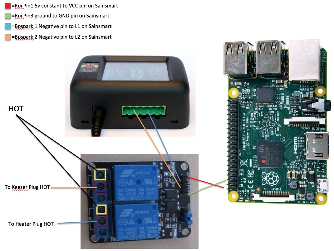
The credit for this goes to @beerwoz, but this is how I wired the relay. After the wiring is complete you would then need to invert the trigger signal through the brewpi devices menu.
You are not connecting GND from Spark to relay board. This only works because the Spark is connected to the Raspberry Pi via USB and through the Pi, the spark and sainsmart board GND are connected.
Alternatively, get GND and 5V from the RJ12 connectors of the Spark (pin 3 and 4).
I advise against using mechanical relay boards like these, because:
SSRs are easier to wire, because they don’t need a 5V external power supply.
SSRs are better suited for frequent switching (for the heater PWM).
SSRs switch on an AC zero crossing, resulting in less electromagnetic interference.
The sainsmart board is only marginally cheaper than 2 SSRs.
SSR VS EMRs varies a lot. Cost is one, the other is amperage. But to be honest, SSRs are becoming cheaper then Mechanical now, and when you look at the reliability, a lot more safer, and how long they can last, there are not allot of applications other then High amp loads, or Hot environments that EMRs beat SSRs. There are some safety systems that Mechanical Pull relays can do better, but this is Industrial PLC and Automation. You can also build your own SSR circuit if you like, but I advise to just used something off the shelf.
For this application, the Zero Cross is safest and best IMHO. I think the term PWM is different then what I am used in the industry, for me PWM is just a change in phase width, this is used to either drive motors directly by changing the RMS value(actual voltage used), or it can drive a proportional SSR(which are very expensive and usually controlled by milliamperage). I think PWM in IoT is just pulse freq, but I do not have a O-Scope at home, I should get one though.
You can get SSRs in smaller packages as well, I know there are a lot of IoT boards with them now.
PWM is not even fast switching in BrewPi. The default PWM period for the heater is 4 seconds. You won’t need a scope.
Fast PWM would not work well with the AC signal.
I would like to use the following board with brewpi to control the brewzilla using the existing brewzilla board. I already have craft beer pi controlling my brewzilla. The voltage the spark would be controlling is 5VDC low voltage. The existing relay board in the brewzilla handles the element load. My plan was to use the spark ground and output one one side of the optocoupler board and the brewzilla 5V on the other side of the optocoupler…making both voltages low current and isolated.
Does any body see a problem with this?