PWM Period: No Control

The PWM can shorten a period if the setting is all over the place.
Example: PWM is set to 30min and 10% and running for 3min high, 7min low so far.
If the PID then ramps up the PWM to 90%, it will not sit out the 20 remaining minutes of low time, but go high as quickly as possible to get to the new target value of 90%.

Can you export your blocks and share them now then?

It sounds like it’s behaving as intended then.
Right now the PID has Ti = Td = 0 and Kp = -100.
I’ve just lowered to 50 to see how it behaves.

Here are my simplified blocks right now:
brewblox-blocks-spark-one(1).json (5.2 KB)
(Same behavior after deleting all block, fresh install and simple set up)

Ended up with decent periods (20m) by lowering Kp to 12.5 and jacking I way up (Ti = 2m). Td is at 4m.

Ti 2m? No wonder you got short cycles. It should be hours. Please share your PID chart.
And read this topic:
https://community.brewpi.com/t/ftss-glycol-setup-brewblox/4299/107

It will give you some insight.

I ended up settling on:
Kp = -12.50
Ti = 1m
Td = 3m

If I set Ti and higher (2h), the temperature would not reach the set point without a large Kp, resulting in the really short cycles.

Here’s the last 10 hours:

Here’s the last hour:

Then use a large Kp.
Ti of 1m doesn’t make sense. In needs to be so slow it is zero until Kp is almost flat.

Seriously, start with only Kp, tweak that until it responds well, tweak ti later.

What kind of setup do you have?

Your derivative is also very high.
Try with both Ti and Td at zero and use only p.

I started with Ti and Td at zero, only setting Kp.
I needed a Kp over 100 to reach the setting when I set it to 32°F.
This resulted in 100% PID output until the temp hit the set point.
Then a sudden change to 0% as it crossed below the set point.
A few minutes later, the temp rushed up past the set point triggering 100% again.
This is what was resulting in 8 minute periods.
It yielded what you accurately described above as “setting is all over the place.”

I am using my old chamber to work out my kinks with Brewblox, before buying the commercial upright freezer for the conical.
I have a 7cu.ft. chest freezer with a fan inside that runs all the time.
The slope of the cooling is pretty steep when it is on, and since the garage is about 90°F, the slope of the warming back up is equally as impressive.

I need more Kp at 32°F than at 50°F and of course 68°F.
I changed Ti to 2hours and was running a bit hotter at 68°F.

Let me get you a graph of the system at 68°F, 50°F and 32°F with just Kp.

Also, I have worked my way through about half way through the thread you linked.
Always enjoy reading more information.
I am not totally new to PID, but I don’t get paid on my PID tuning skills either.
The response of this freezer being so strong and the heat of the environment
are making it a bit of a challenge for me to recognize any patterns here.

That’s exactly what the integral will do for you. If the p value is not enough because of a constant external temperature influence, you need a constant amount of cooling, independent of the temperature error.

So you need a low Kp, because it is so strong.
And then you need to set Ti long enough and give it time to build up.

If Kp is too high, anti windup will keep the integrator at zero. Anti windup is triggered when the achieved actuator value differs a lot from the setting. If the setting fluctuates too fast, this is inevitable.

You had a too high Kp, too short Ti and too long Td. All factors that cause a fast changing output.

Saying you need a high Kp because you have more constant temperature loss does not make sense. The integral is for steady state losses.

1 Like

Having been through this journey recently and finally got my head around the whole PID concept I dont know if I can offer some advice. Elco referred you to a post in one of my topics where i was trying to tune my system

  1. By having a short Ti period all you are in effect doing is allowing the integrator to build up extremely quickly and effectively add a whole bunch of extra duty onto your output that really should have been determined and set in the first instance by the setting of your Kp value
  2. You should set the Kp to a value that without any Ti or Td gives you a small amount of overshoot on your setpoint.
  3. Once you have the Kp value at a point where you are only getting a small amount of overshoot you can then look to be tuning the Ti and Td
  4. Adding a small amount of Td and trying another cooling cycle(Getting down to setpoint in the first instance) and seeing what value prevents you from overshooting helps you to get your Td value dialled in.
  5. You really don’t want your Ti to be short otherwise it can also lead to overshoot for the reasons I mentioned above it will build up quickly and set your Duty beyond what is required.

You mention in your reply as i’m typing the below

This is because of what Elco mentions below and also, if it didn’t do this then your temperature would not be maintained. If the gain in heat due to the environment is high in your case because of the external temperature then in order to maintain temperature the compressor must come on more often otherwise your freezer would bring things down to setpoint hang around for the period you want to protect the compressor by which point the temperature would be way above setpoint, then it would kick in again and bring it back down to setpoint and end up in a osicllation pattern of setpoint high setpoint high.

You mention you have a used an inkbird but all that is really doing is turning on the freezer bringing down to setpoint and then based on your compressor delay setting in the inkbird telling the inkbird to not allow the freezer to come on again for a period of time that you have told it not to. In the mean time the temperature will fluctuate as a result. If you dial in the compressor delay then sure you maintain a setpoint temperature but if you were graphing the temperature changes over time with an inkbird i’d be surprised if it wasn’t fluctuating allover the place.

Anyway if I can help by sharing any more of my experiences then i’m happy to do so.

For info I now have my system maintaining a temperature differential of around 0.04c across cooling and heating cycles.

{Edit: and the best advice I got from both Bob and Elco that made the biggest difference to my understanding of whats going on in Brewblox is to not get fixated on the Ferment graphs, sure they show you the temperature changes but watching the pid outputs and the pid graphs live are what made the lightbulb click for me. I actually ended up having a couple of browser sessions open where i had all of these open and so could just flip between them and watch what was happening as i ran my cycles. Also Elco and Bob will will be able to advise far better than me but what good looks like for me is where My Output Target (P+I+D) and Output Value closely follows and maps to P following the initial spike when cooling is requested, if you look at your cool PID graph in post 25 you will see that is not the case you’ll also see that same pattern reflected 9:30 on-wards in your graph as its trying to maintain temperature, this is an indicator that your duty is being skewed by I+D }

2 Likes

Thanks for adding that!

Another important point I guess is to tune Kp at a temperature around ambient. Steps of a few degrees around ambient.

Kp should ideally be tuned without external disturbance. It should depend only on how quickly the process itself responds to temperature changes caused by the actuator alone.

1 Like

Thanks everyone, for huddling around this to get me going!

Here’s the last 2 hours set to 68°F, with Ti = Td = 0.
This is following a free rise from 50°F.
I have Kp = -12.5.

I am getting ~18 minute periods.
PWM is set to 30 minutes.
What’s the opinion on my Kp value? Too high? Too low?
Why does the average temp keep climbing?

So the plan to tune around ambient temp is something I have not done.
I have been trying to tune at 32°F, the most difficult case.
Once I realized how different it was than 50°F, I tried it there and 68°F.
Ended up chasing my tail a bit.

I’m going to shut it off, open it up and let it get to ambient temp.
Night time is cooler than day, so I have a good stretch ahead of me.
I plan to set the set point to 5°F cooler than ambient once it settles.
Is Kp = -12.5 a good place to start?

Again, really appreciate your thoughts.

by the way, here’s the ugly duckling:

Ok so my first comment would be this.

What is the temperature probe measuring the temperature of. It looks like it’s measuring the temperature of the air in the freezer?

Apologies if I’ve got that wrong I’m just going on the pictures! I can see two probes I think!

If it is measuring that then that’s not going to work way too variable! You asked why the temperature is going up, well for a start although that fan in their is circulating the air, it will also be generating heat which will effect temperature variability.

Again you’d need to put something like a jug of water in there and place the probe within that and then do you’re testing based on that temperature reading. Remember with a fermenter in there you’d have a probe in a thermowell measuring the temperature of the wort or in the wort or taped to the sidewall of the fermenter and measuring the effect the cooler air has on dropping the temperature of the liquid and it would be much slower than 30 minutes.

I don’t know enough about the ins and outs of brewblox algorithms but you’re asking a lot of any system to deal with that type of temperature variability in air, with the equipment your using!

Apologies if that’s not what your measuring the temperature of and ive gone down a rabbit hole here :grin:

You’ve got it spot on.
I’ve got two sensors, one will stay in the air, the other will go in a thermowell.

I am not worried about a fluctuating chamber temp.
What matters is the beer temp.
I am sure the beer temp will be rock solid, just like it was with the fluctuating inkbird, that is essentially P only.

I am tuning the chamber temp right now with the ‘constant chamber temp’ action before moving on to the ‘constant beer temp’ action.
I am sure I could tune the beer PID with the chamber temp the way I had it, and get great results.
I am always open for learning more though.

The ambient temps settled tonight at 83°F.
I will set the set point to 78*F and see what I get.

I started with a low value of Kp = -6.25.
Everything stable at 83°F, set point set to 78°F.
On the first cycle, the temp does not reach the set point, but it does on the second.


I’ve tried it with a few incrementally larger values of Kp and barely walking it in.
Should I be aiming for the first cycle to hit the set point?
I think yes, so I’ll chase that tonight…

It is not our goal to hit the target after the first high cycle. We just want the right average value, the percentage that it is enabled. Think of PWM not as a digital actuator, but an analogue one. The on/off cycling is just to convert something that’s only 0/100% to something that can do 0-100%.
With a 30 min period, it cannot adjust very quickly. A smaller period makes it more fine grained in time. But we’ll have to work with the limits (minimum off time) of a compressor.

You can see that your process is difficult. It has a lot of lag. We can’t cool until we’re there, because it will fly past it afterward.

Try a shorter PWM period to have smaller fluctuations.

I would also try moving the sensors down a bit, not this high in your collar. It is a bad reflection of the actual temp. Cold air sinks. The collar will also heat up faster.

The Kp value looks alright, but try with the sensor placement a bit lower.

1 Like

I think I just had a moment of enlightenment!
Thanks for this last nugget @Elco.
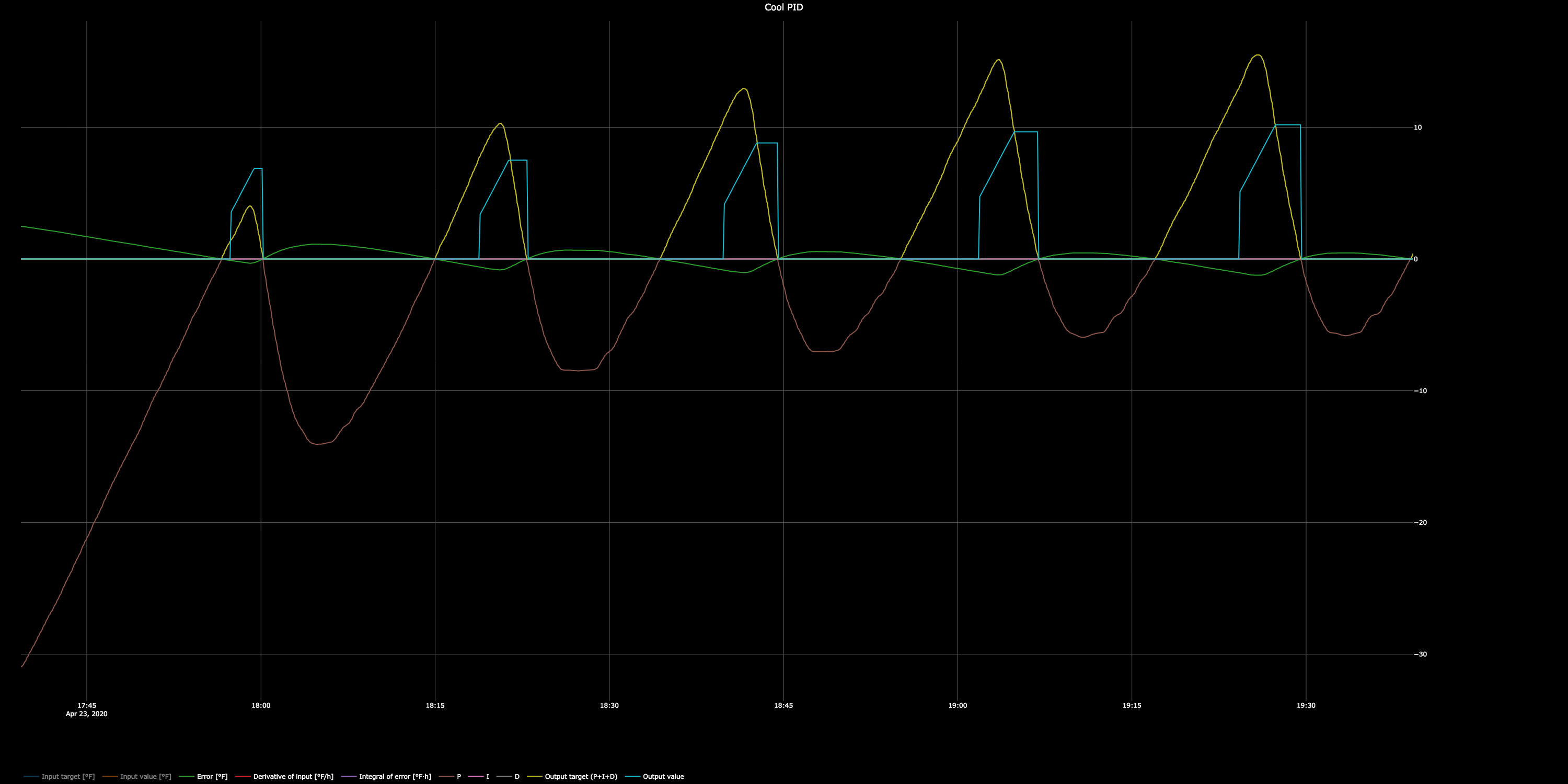
I should be seeing how the PWM duty responds to the PID settings, not the actuator and temperature.

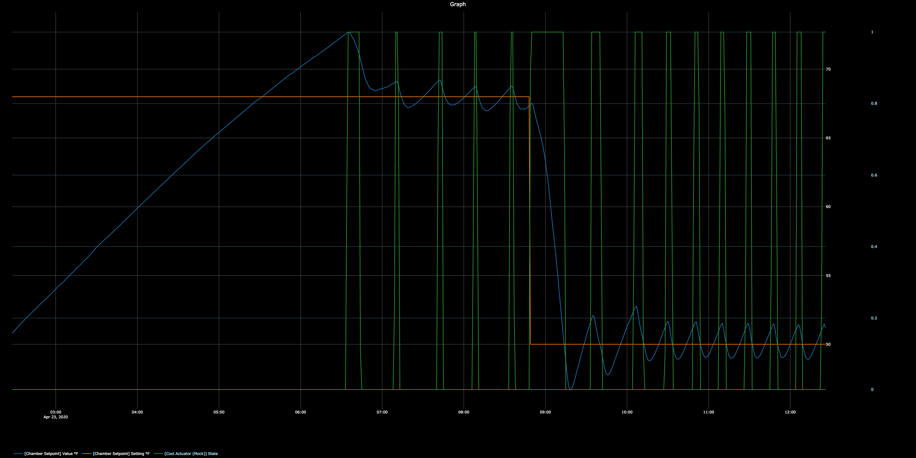
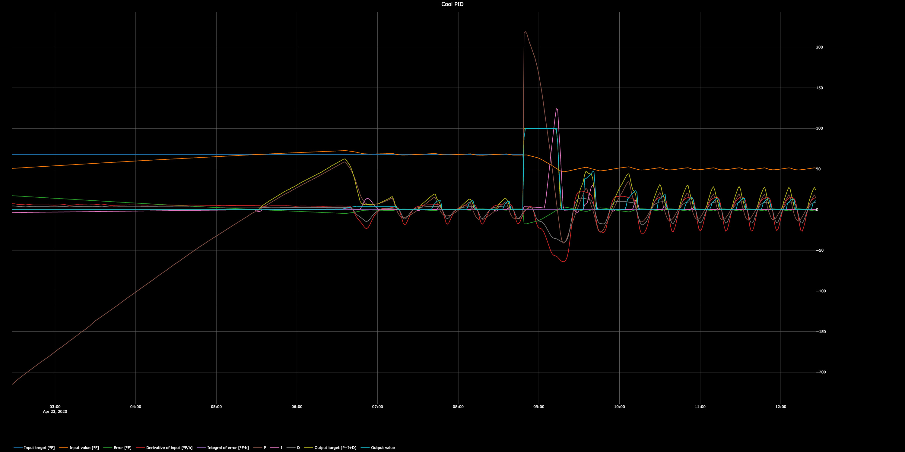
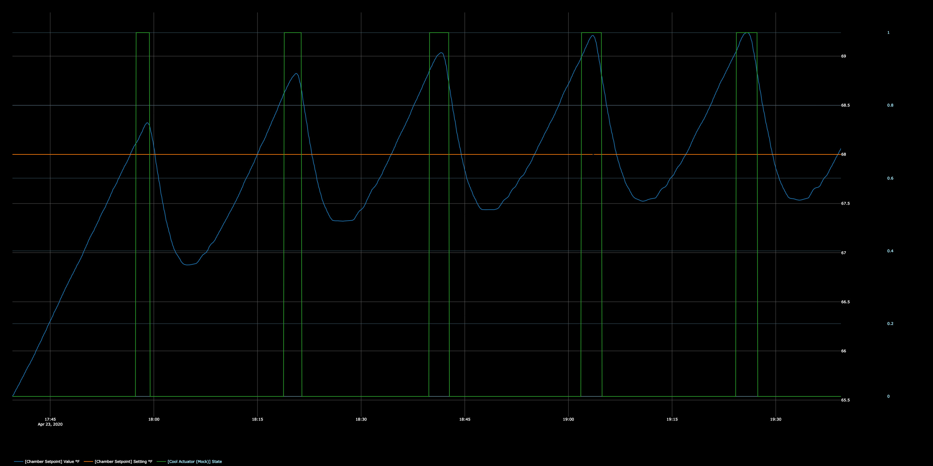
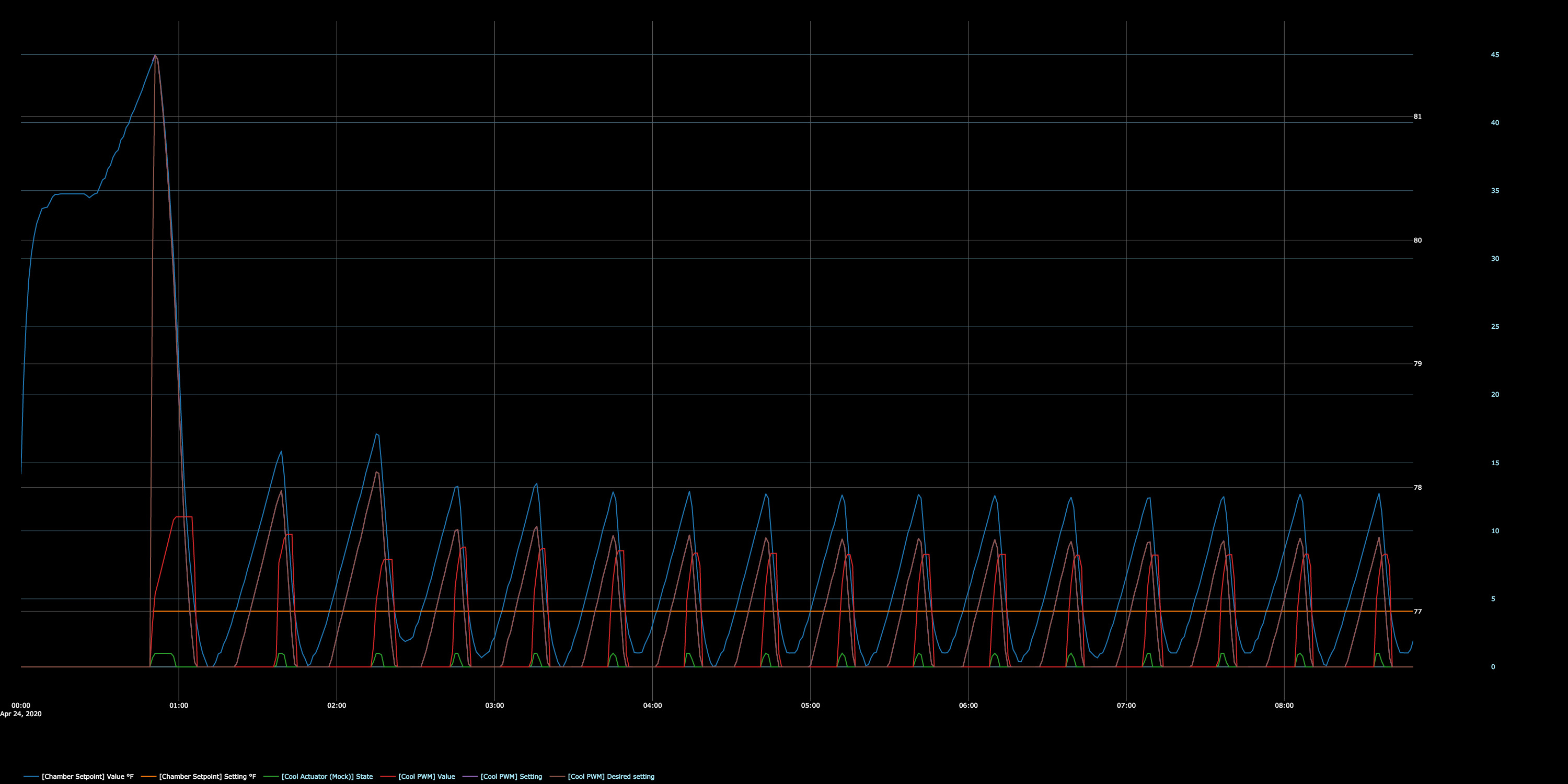
Have a gander at this graph from last night where Kp = -10.


Ambient had cooled off to ~81°F. Setpoint = 77°F.
I am thinking the PWM desired setting is what I am tuning for here.
After the initial cycle, the next two cycles have a higher PWM desired setting then the steady state.
I can’t tell if this is because the system is too slow to respond (Kp too low) or because it is ringing (Kp too high).

A couple more theoretical questions…
When discussing setting appropriate Td and Ti durations, the time it takes for the system to settle and system response time is discussed.

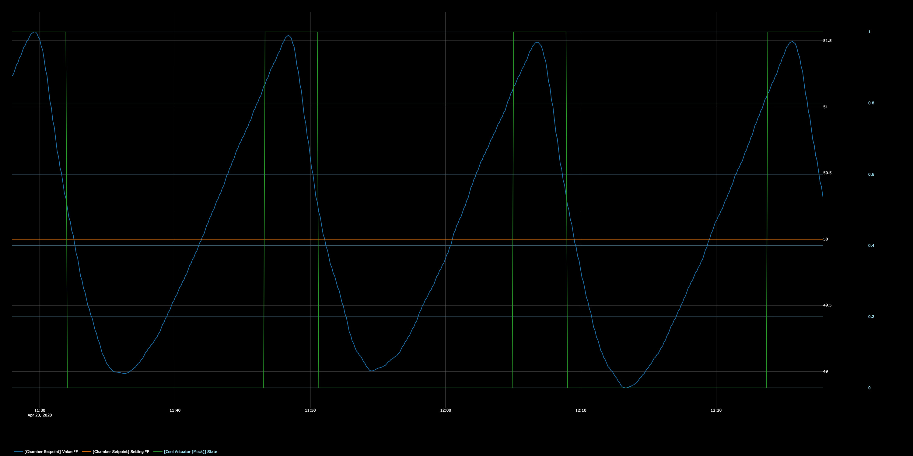
On this graph I posted above, is the time it takes for the system to settle measured from the initial cycle’s actuator off time until the temperature first goes horizontal?

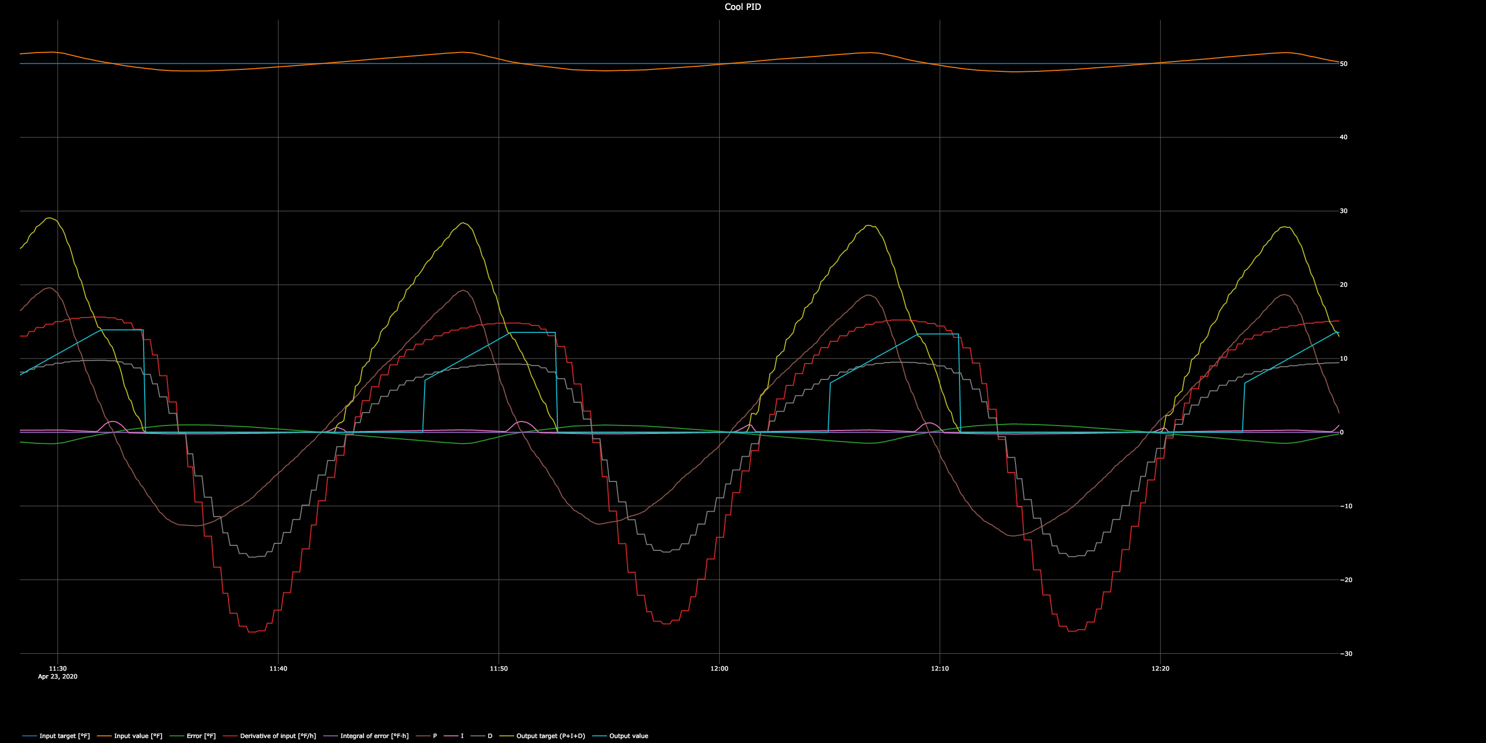
Or is it from the actuator off time until the steady state PWM desired setting is achieved (3rd sawtooth after the initial cycle)?

What about system response time?

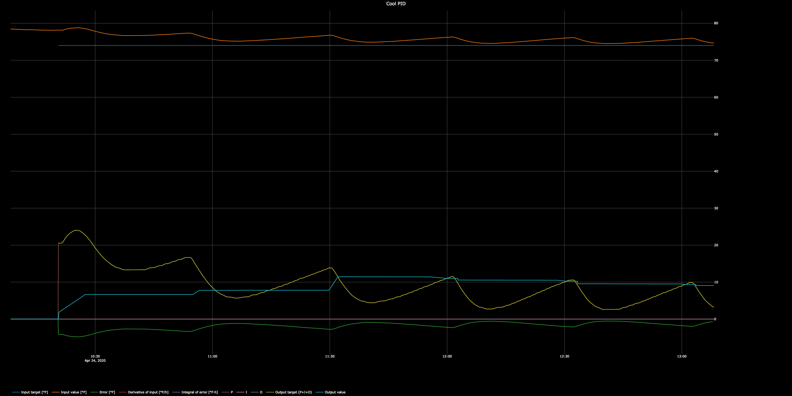
It would be helpful to see how you would deduce Ti and Td from this graph.

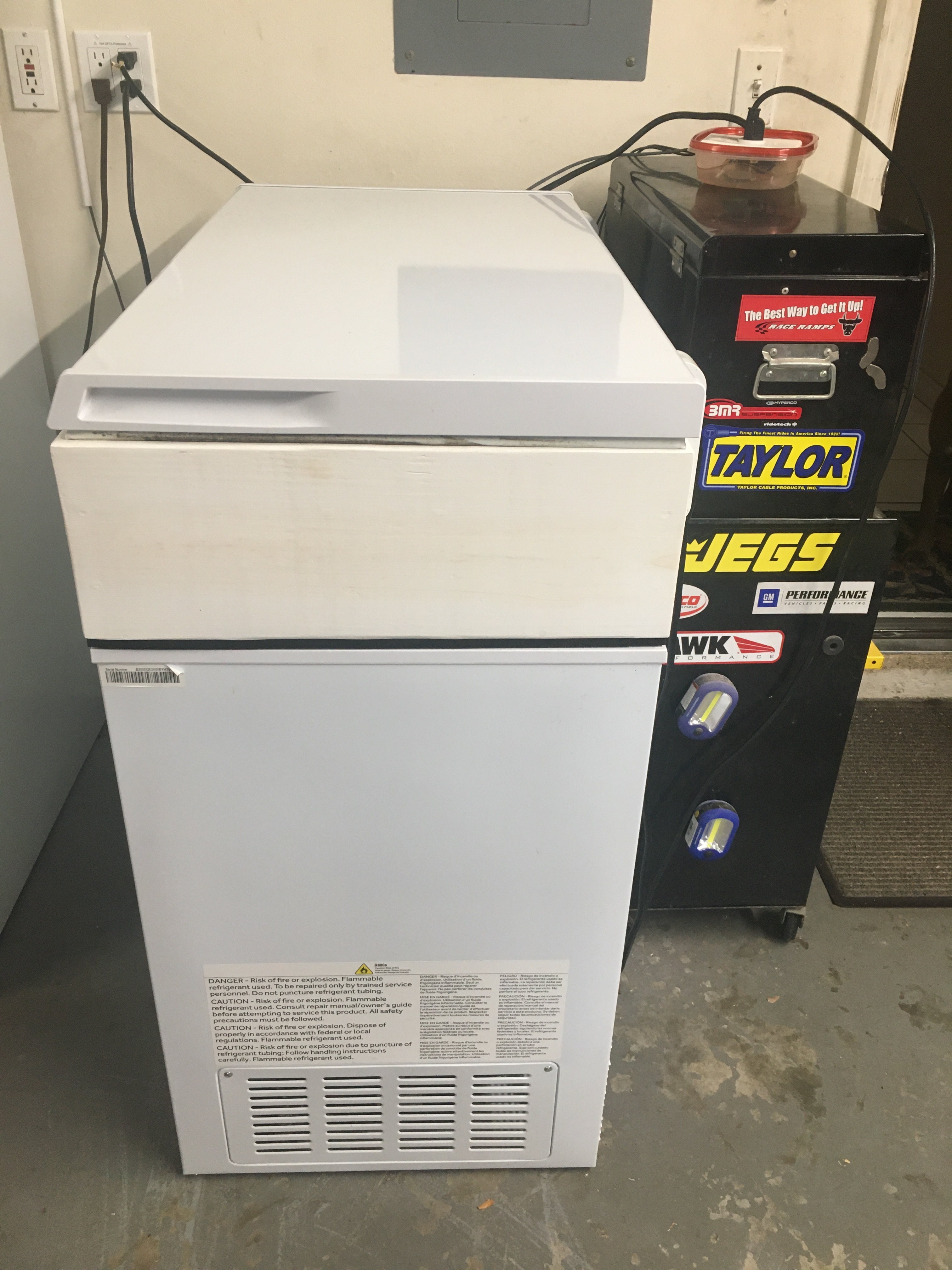
Regarding sensor placement, you are absolutely correct.
I froze 3 kegs of beer about a year ago because of this; sad day.
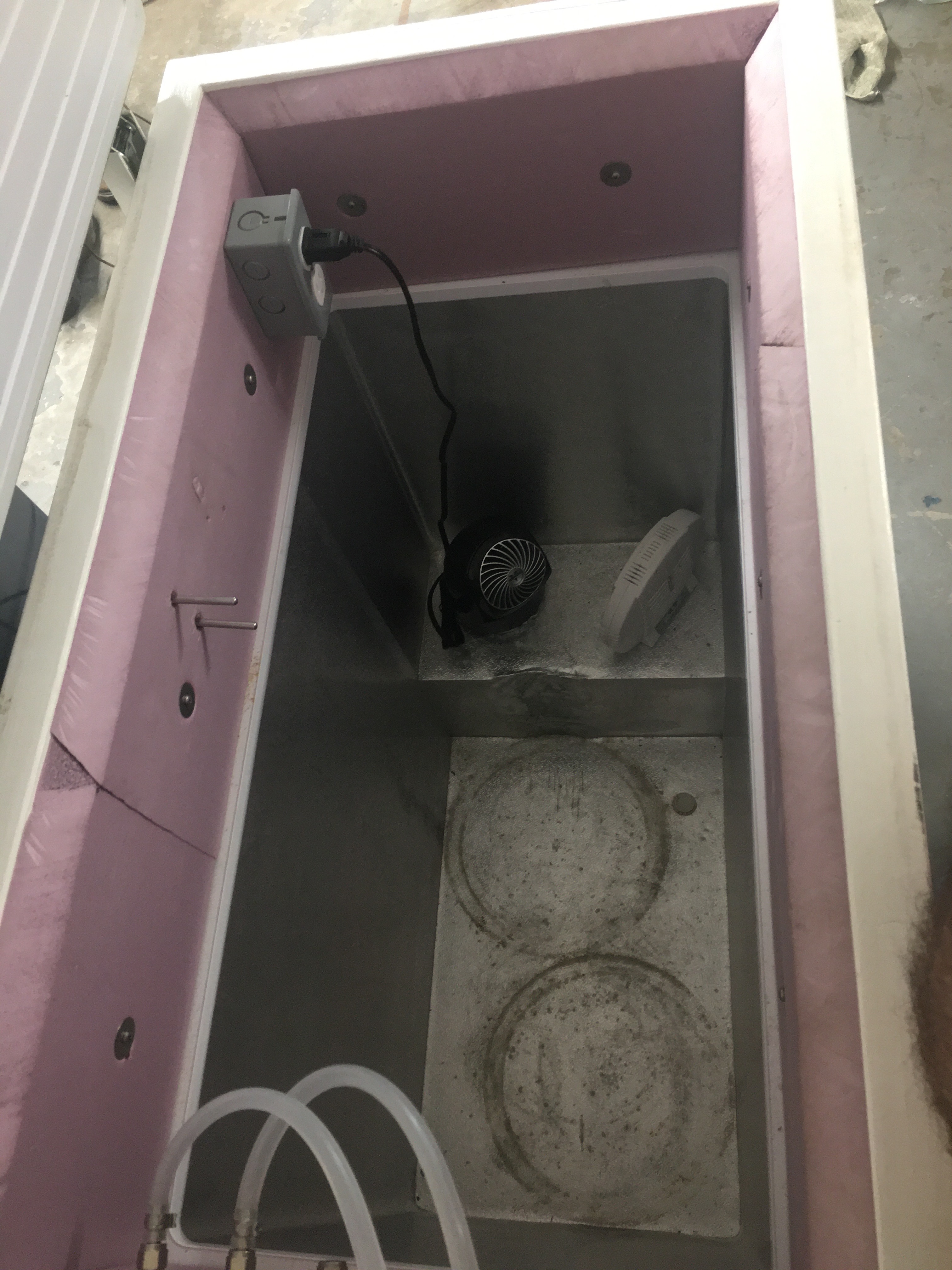
I found about a 10°F difference from the top of the freezer to the bottom.
I left one sensor where you see it know, and placed the second in a thin plastic ball resting on the bottom of the freezer.

Adding the fan that blows very hard at an angle (azimuth & elevation) reduced the temperature difference to less than 0.1°F.
And it is pretty much instant.
If you open the lid the two probes would drift apart.
Closing the lid, the two stabilize within a couple of seconds.
I’m convinced probe placement is not an issue here (with the fan on all the time).

I think your fan is generating a lot of heat actually. How many watts is it?
I would definitely try without the fan. Or put the fan on PWM too.
Only let it run occasionally, limit how much heat it generates.

Try Kp at 20% of what it is now. And set Ti to 6 hours. Keep Td at 0.

And look at the PID graph instead. Go to the PID block, and open the graph from the block.
It is also possible to filter the fridge temperature in the fridge setpoint, to smooth it out.

I had already cut Kp in half and started a new test; Kp = -5.

Looking at this graph, I feel Kp = -5 is too small because:
a) the temp never reaches the setpoint
b) the output value only hits 6.6% after the first cycle on time, but it seem to settle out at about 9%.

I also think that in the last graph, Kp = -10 was too large because the output value was oscillating. Somewhere in between is the answer. Kp = -7.5 is up next, and almost exactly what you suggested just by looking at the first graph. Lucky or good?

Why/how did you recommend Ti = 6 hours?

The fan is 120VAC/0.24A (28.8W).
That is an appreciable amount of heat, but I usually have to supplement it with a 60W bulb for the winter.
I am alright to live with it and its resultant fluctuations for now.
I do not think they will present a problem for a steady beer temp.

The temp probe is filtered to 90s. I settled on 90s because while there was great improvements from unfiltered to 90s, I didn’t see much change other than the delay going up from here.