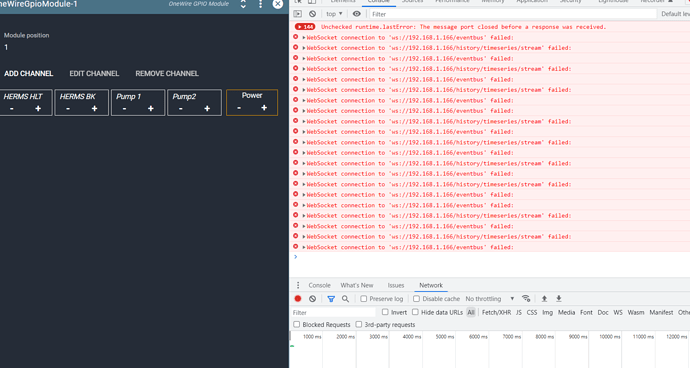
I don’t see anything in the network tab for assigning channels
It’s complaining it can’t connect to the backend, and earlier the log had some errors about its cert.
You may want to run
brewblox-ctl makecert
brewblox-ctl restart
Then hard refresh the UI (ctrl-F5), and check whether the channels are still assigned.
And to clarify: the idea was to keep the network tab open, and then in the brewblox UI assign the channels. The network requests will show up in the network tab, and can then be exported.
This suggests that the channel is now assigned. If all blocks in the chain are linked, they should now toggle the relay.
I did try that but nothing happened still, either with the relays or valve boards - So moved back to the spark 3 for the time being - until i figure out what I have not done right.
A few questions on the spark 4 - if I attach 12v input to the pins only - no usb-c it powers up spark, will that enable 12v to each of the boards?
Before I had a raspberry pi p/s connected to usb-c , it showed all valves, sensors, ssrs, but did not run any of them, so assuming that the p/s was not supplying enough power.
Many thanks
All GPIO modules share external power, so connecting 12V to any module will allow all modules to use it.
Every module has a setting to switch between 5V and external power in actual output.
Thanks Bob, still a little unclear to me.
If I attach 12v to a module, but the gpio modules are set to standard 5v (enough to trigger the relays), do the one wire connection to the valve boards operate at 5v, or the 12v plugged into the power pins of the module. I was thinking that the valve boards were not triggering the valves as they were not sending correct voltage - but all seemed ok on dashboard and all leds were active.
Ouput will be 5V. You mean the DS2408 valve control boards?
Yes the DS2408 boards
I see also there is also an option for 2 port or 10 port boards - I have never seen them for sale, are they going to be available to buy?
There’s some demand, so we may bring them back, but we designed the GPIO module to be a replacement that doesn’t suffer from their drawbacks.
If a onewire extension board loses connection, it can be left stuck open.
We’re considering how to either deal with this problem, or to make users sufficiently aware that they can install their own safeguards.
I like the idea of moving away from onewire, but do not know how I would wire up the new gpio module to drive the 5 wire ball valves. Can it be done?
Yes, the GPIO module can control valves. Do be aware that there’s an issue right now where inrush current causes the module to error out due to overcurrent. There’s a workaround with a resistor, and next patch will include a software fix.
Thanks Bob, do you have a diagram on how to wire these valves into the gpio module. I assume you would just wire the +ve to 8 pins - 2 modules - but not sure how the other 4 wire are configured.
Many thanks
Electric Ball Valve - Losing Power on GPIO Pin should be a useful reference, including discussion on how to work around overcurrent problems.
Good afternoon
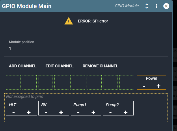
Not sure if I am in the right place, but I guess two questions - I am trying to rebuild a system, that I think I broke by shorting something - Got a new GPIO and am confused how to assign the input voltage - i.e. power on the last pins.
I See this

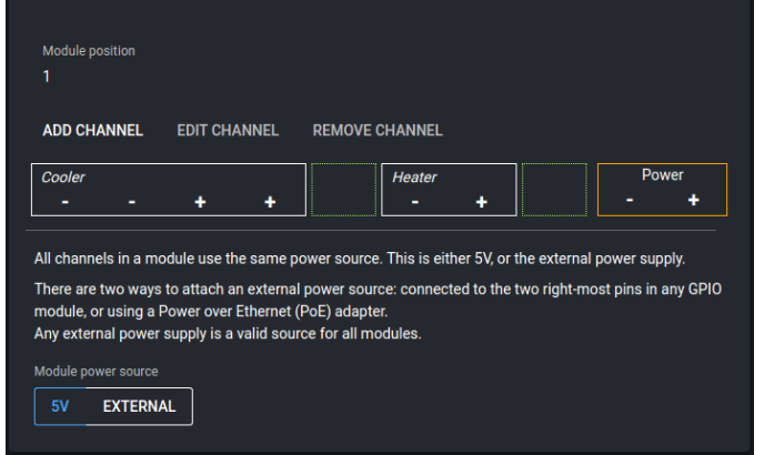
But previous posts have this

So is there anything that explains how to attach 12v connection, or is this Something to do with SPI Error?
Brand new GPIO, so trying to figure out if I have not understood how to configure it, or whether it needs to be done differently, or if I have pooched the spark. Any ideas, getting bored with drinking Heineken.
Thanks in advance
I can’t conclusively say at a distance whether you already fried the module. You provide input voltage to the Spark by attaching the leads to the separate right-most terminals, as indicated by the orange block. After doing so, you switch that toggle in the second screen from “5V” to “External” to use the external power supply you just connected.
SPI error suggests that there is no communication at all with the module. If this is a new module, it is likely that the spark 4 is also damaged.
OK, thanks - I will order another Spark.
Regards
Warren
