Hi!
I am currently working on a HERMS setup and when doing some testing, I found out that the pumps from BrewPi are really, really quiet. This is ofcourse great, but twice I forgot they were still running while disconnecting hoses.
In order to give me a visual reminder the pumps are running, I want to add LED’s on my conrol panel. The LED’s I like however, are 24V LED’s. In an other thread on this forum, Elco suggested to use DC-DC SSR’s to solve this issue.
My electronics knowledge is a bit rusty (and I am an amature), so I would like to ask if somebody would be so nice to confirm my connections are correct.
What you see:
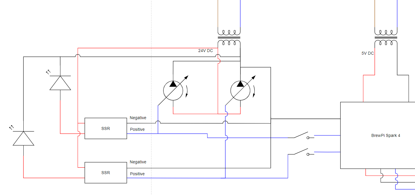
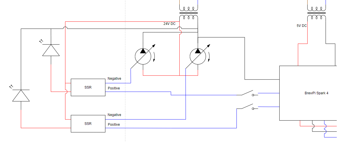
5V transformer to feed the BrewPi
24V transformer to feed the pumps
The BrewPi sends a PWM signal to a manual switch (to disconnect without having to reach to the laptop in case of forgetting to turn something off) that goes to the + input of the SSR. The - input of the SSR is then linked to the Pump to deliver the PWM signal (so the PWM signal goes through the SSR). On the other side of the SSR, the 24V + is switched and in this way, the LED is switched.
The pump ofcourse gets a +24V and a ground from the 24 transformer, as well as a ground from the BrewPi to sync the relative grounds.
Really hope somebody can tell me what I have done wrong (or that this is correct ![]() ) Thanks in advance!
) Thanks in advance!