I am building a BrewPi fermentor with arduino uno + raspberry.
For the arduino I would like to build a shield for connecting everything.
Now is my question what is the current connection diagram for the latest firmware for arduino uno (0.2.1 I think?)
The schematics I found on this forum are different, one is with SPI for the LCD other one with SPI etc.
I cannot find out which is the correct one.
If somebody can tell me what the correct connection diagram is I can continue, or if someone still has a official brewpi shield that is fine with me as well!
1 Like
Also looking for the right diagram. Can’t figure how to make brewpi read temp sensor without connecting the relays. I can make the arduino uno rec C read temperature with DallasTemperature code uploaded to it at pin2 on the digital side of the board. When I follow the diagram to conenct to brewpi I get no devices in the maintanance page. Seems like the onewire bus does not read.
To make this short: Want to just connect the probes without the relays and only show temp for now but doesn’t seem to work. Do I need to connect the relays to make it work? Seems a bit oud.
Can anyone help with this?
And sorry if I’m hijacking this thread but it seemed to fit 
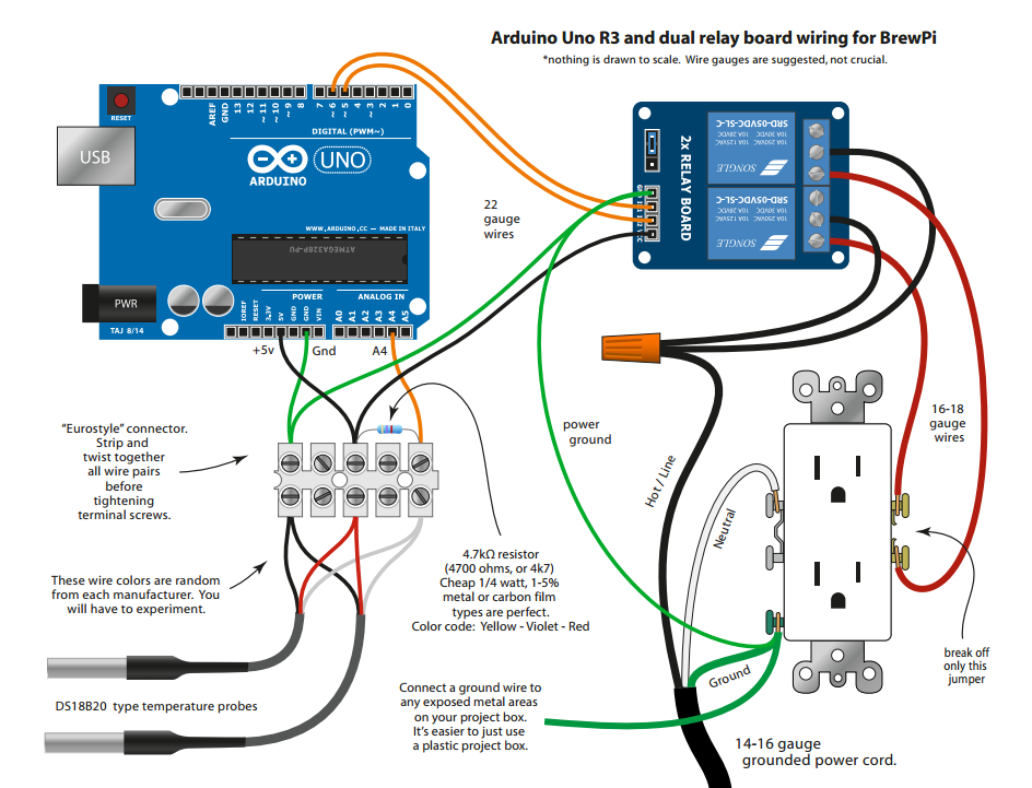
You need to connect the temperature probes to pin A4. They also need 5V and ground, and a 4.7K resistor between 5V and data.
1 Like
You need the 0.2.10 hex file and you need to connect your probes to A4.
You should also make sure you are not using parasitic sensors, BrewPi does not support those. There is a sketch somewhere that tells you whether yours are parasitic only, but I don’t have a direct link for you.
Please not that the Arduino version has been end-of-life for over a year and is no longer supported.
Thank you for your quick reply.
I’m aware of that the arduino version is not developed anymore but since I had both an Arduino board and a Raspberry pi lying around at home I thought I would give it a try I use the 0.2.10 hex file.
I’m using DS18B20 fro kjell.com. Datasheet are to be found here:
https://www.kjell.com/no/.mvc/Document/File?id=baba25dd-e4df-4ec0-84c0-a6d3009a62d1
I think, based on the datasheet that this sensor can be run in both parasitic mode and none parasitic. Why is it so that when wired as non parasitic it will still not work with brewpi when it works with arduino in general?
EDIT:
Also, the probes you sell on your site, are these non parasitic only?
Also found answer to the question regarding parasitic mode in another thread:
https://community.brewpi.com/t/ds18b20-oddities-clones/1656/4?u=andreashv
For others in need of the code to find out
#include <OneWire.h>
#include <DallasTemperature.h>
#define ONE_WIRE_BUS 18
OneWire oneWire(ONE_WIRE_BUS);
// Pass our oneWire reference to Dallas Temperature.
DallasTemperature sensors(&oneWire);
void setup() {
Serial.begin(9600);
sensors.begin();
}
void loop() {
Serial.print("Parasite power is: ");
if (sensors.isParasitePowerMode())
Serial.println(“ON\n”);
else
Serial.println(“OFF\n”);
Serial.print (“Detected “);
Serial.print(sensors.getDeviceCount(), DEC);
Serial.print(” devices\n”);
byte deviceAddress[8];
for (int i = 0; i < sensors.getDeviceCount(); i++) {
sensors.getAddress(deviceAddress, i);
Serial.print("Device “);
Serial.print(i);
Serial.print(” is a ");
switch (deviceAddress[0]){
case DS18S20MODEL:
Serial.print(“DS18S20\n”);
break;
case DS18B20MODEL:
Serial.print(“DS18B20\n”);
break;
case DS1822MODEL:
Serial.print(“DS1822\n”);
break;
case DS1825MODEL:
Serial.print(“DS1825\n”);
break;
default:
Serial.print(“Unknown\n”);
}
}
delay(1000);
sensors.requestTemperatures(); // Send the command to get temperatures
delay(750);
for (int i = 0; i < sensors.getDeviceCount(); i++) {
float temp = sensors.getTempCByIndex(i);
Serial.print ("Sensor ");
Serial.print (i);
Serial.print (" ");
Serial.print(temp);
Serial.print("\n");
}
Serial.print("\n");
}
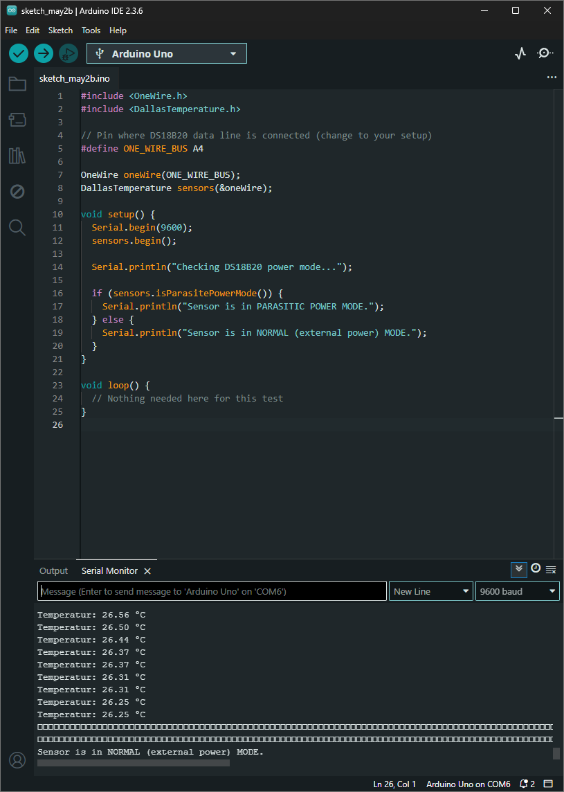
Found that the earlier provided code did not work. Here is an updated one
#include <OneWire.h>
#include <DallasTemperature.h>
// Pin where DS18B20 data line is connected (change to your setup)
#define ONE_WIRE_BUS A4
OneWire oneWire(ONE_WIRE_BUS);
DallasTemperature sensors(&oneWire);
void setup() {
Serial.begin(9600);
sensors.begin();
Serial.println(“Checking DS18B20 power mode…”);
if (sensors.isParasitePowerMode()) {
Serial.println(“Sensor is in PARASITIC POWER MODE.”);
} else {
Serial.println(“Sensor is in NORMAL (external power) MODE.”);
}
}
void loop() {
// Nothing needed here for this test
}