I think there is a difference between the static plate chillers (where there is intentional ribbing" ) and the “gaps” there exists in stainless steel tubing. I think one of the big differences there would be that the ribbing in the plate chiller is quite a bit sharper as compared to the smooth stainless steel portions.
yes, the backflushing is a great idea! i’m thinking of a way to do exactly that, to “soften” up the pieves with a slow flush with hot water, then a backflush with hot water at full speed… I’m thinking of building a seperate circuit for it or something like that, not quite sure yet
not sitting on my thumbs…
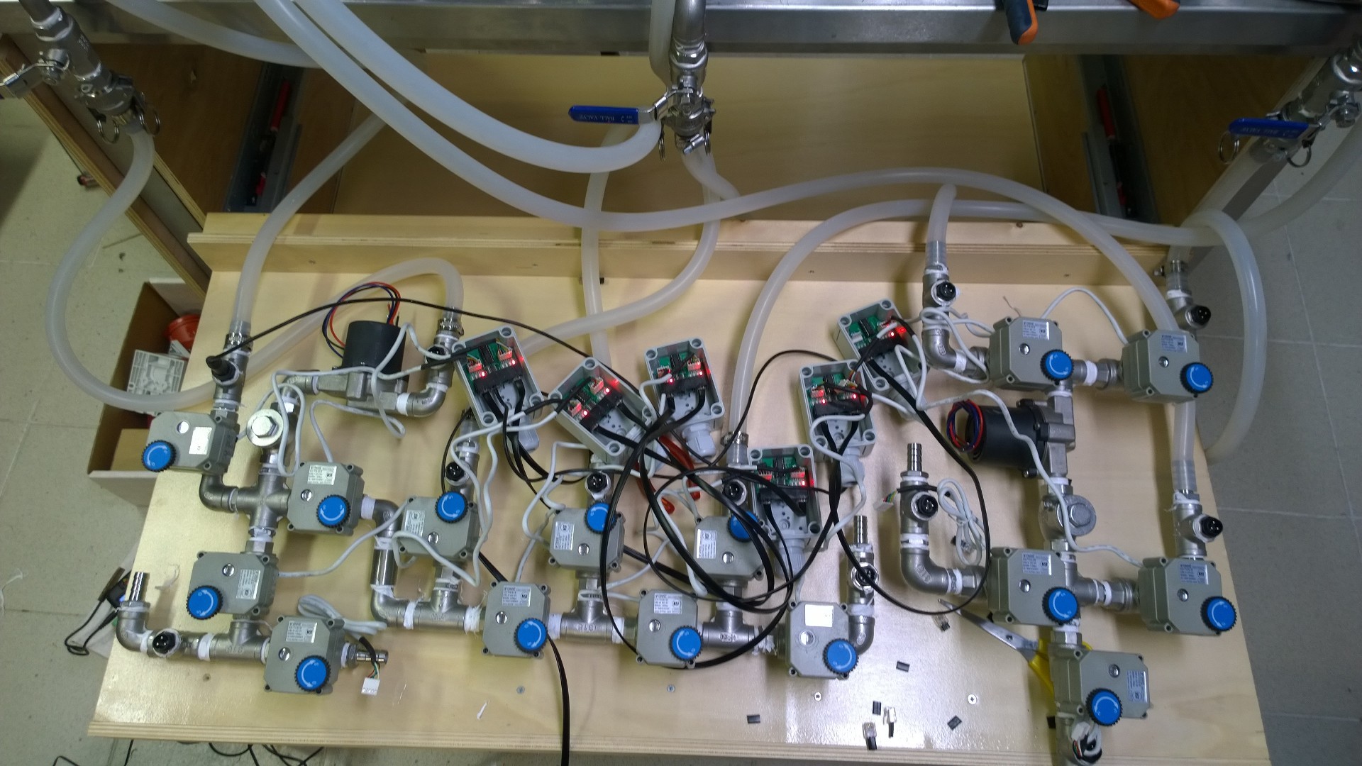
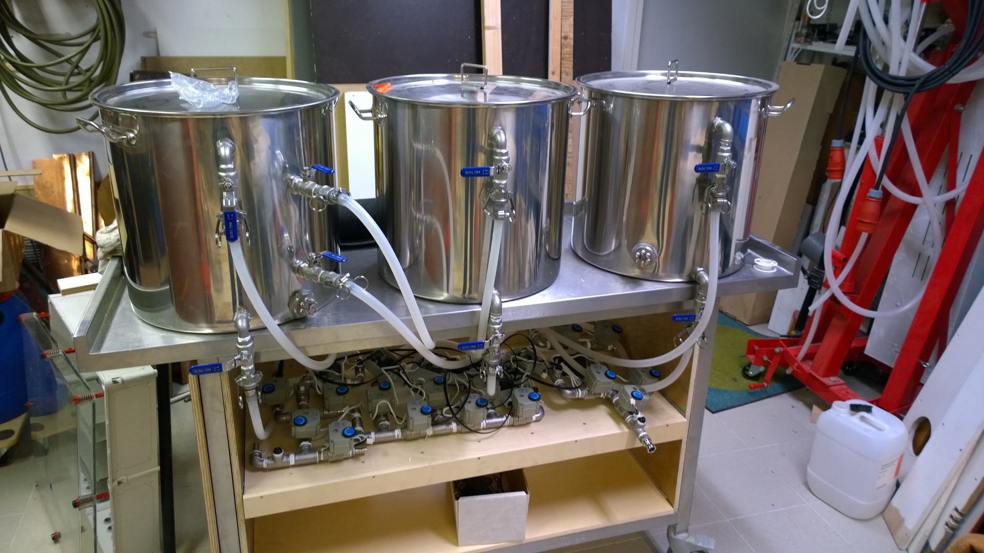
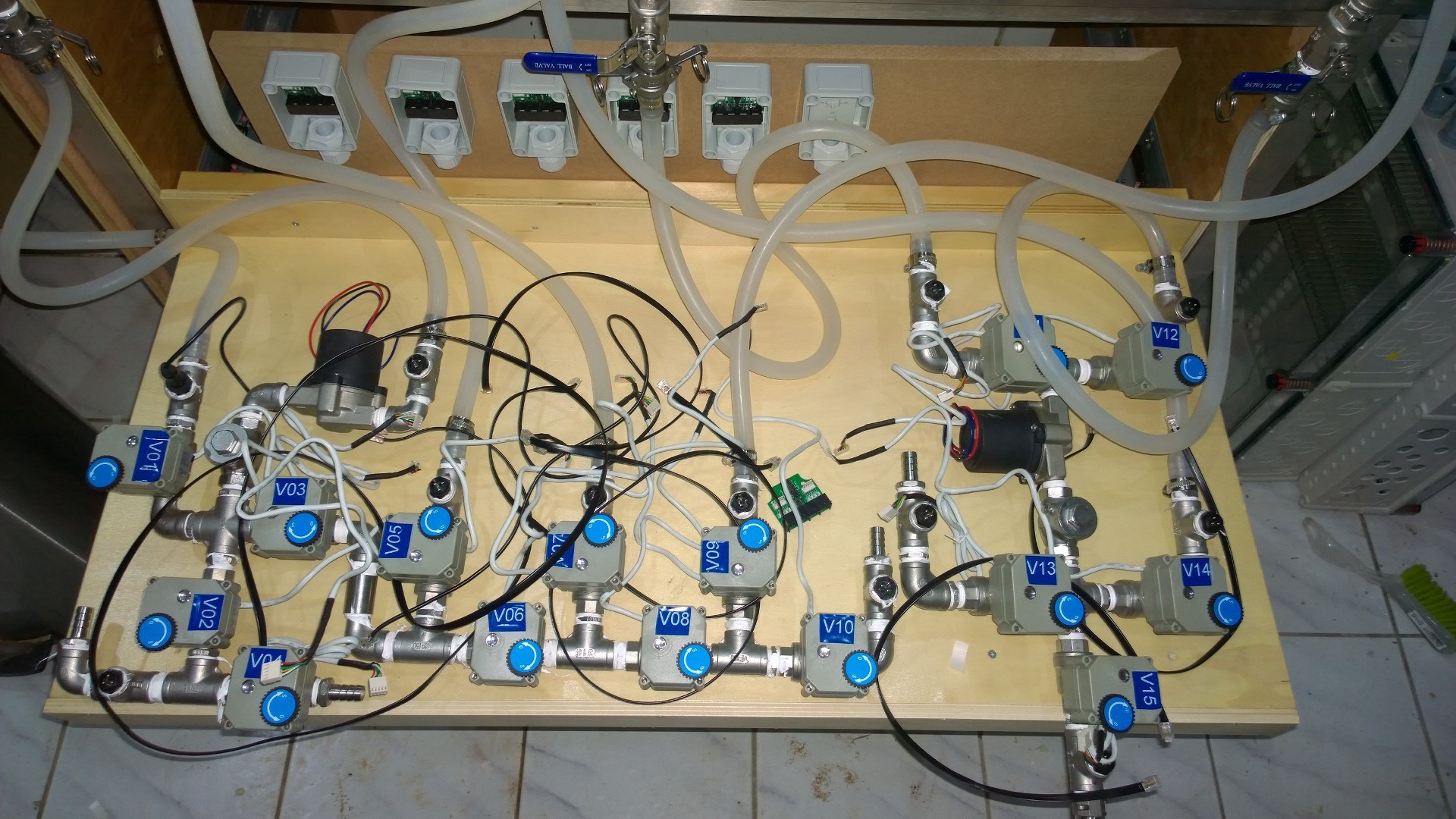
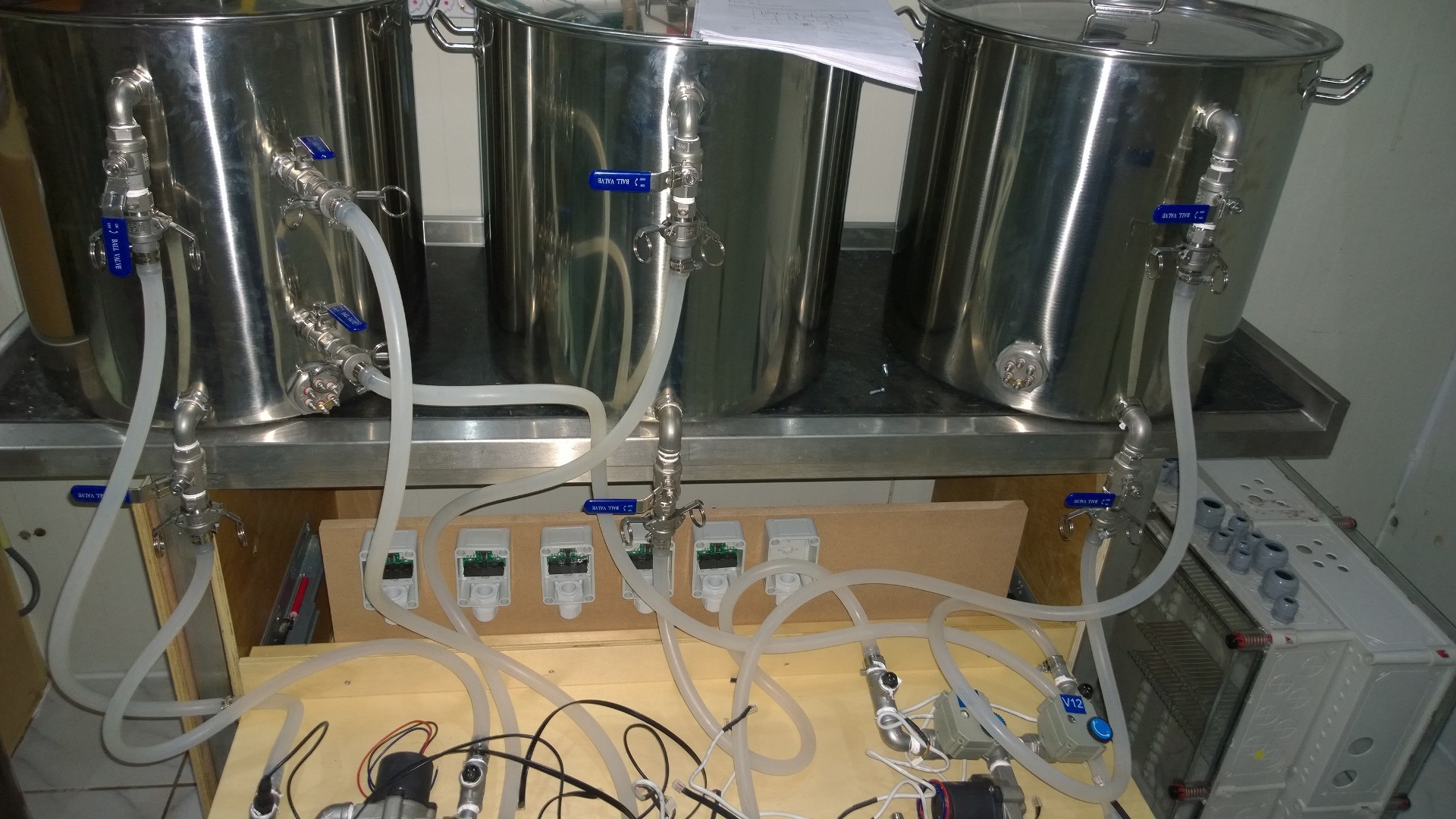
finishing the 3 clusters today and hooked them up, ready for a test run… unfortunately, one of the valve boards had a broken valve connection and I fried my photon… so no test run
so, been quiet for a while… but stuff has sorta happened
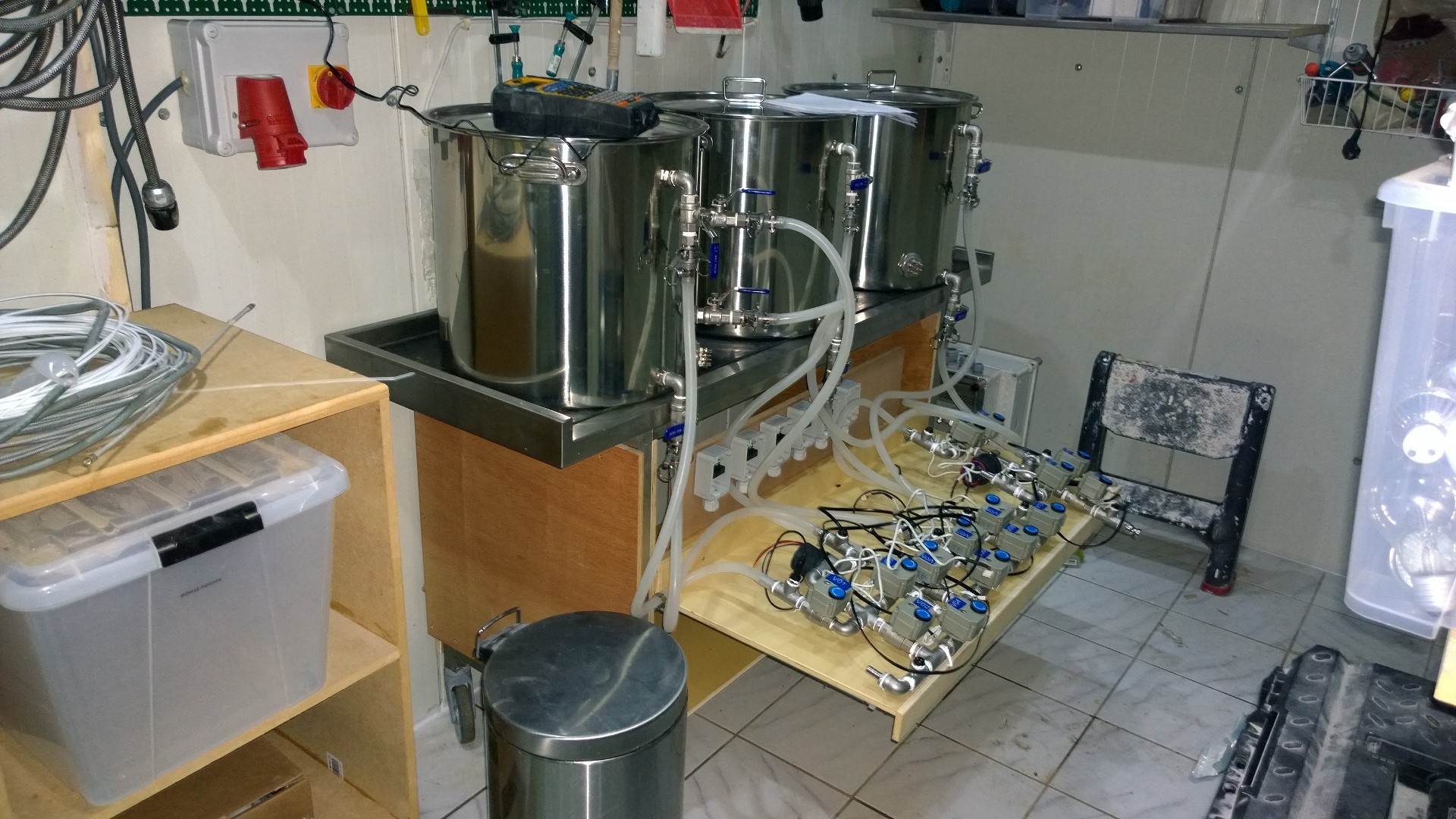
first of all, i moved everything into my shed, i made sure the floor and walls are waterproof so i can spill, and i cleaned a lot of stuff up. also working on getting the control panel build, which is a big thing, getting power to the shed (3 phases) and clean water.
to do is finish building, getting a drain installed and getting a vent installed… so some pictures to proof I’m still busy
also thinking of getting 2 conicals so I can ferment 2 beers at the same time… difficult decision…
So I wanted to follow up with you guys @korneel@cke11y with the Brewpi Spark v3 and the Brewblox setup build. I Have a very similar setup to these pictures except I am using propane instead of electric for my heating but wanted to know if you guys have messed with the system and how you incorporated the electric ball valves and the relays for the individual equipment like the pumps, heater, etc. I currently got all my temp sensors registered/identified and labeled & now I’m trying to figure out the rest of it. Sorry for the N00b questions, but thank you for your time and assistance.
Let me answer it this way, I have it setup to where the transformer is activated by the relay based on temperature and where it is in the process of things. Here is a link based on what I’m doing.
Here is the relay board info: https://images-na.ssl-images-amazon.com/images/I/91AHtk3PT3L.pdf
Input control signal voltage:
0V - 0.5Vdc, low level, relay not action.
2.5V - 24Vdc, high level, relay action.
Input control signal high level current:
2.5V: 0.1mA.
5V: 0.35mA.
12V: 1.1mA.
20V: 1.9mA.
and the transformer is a Application:
24v Controls VA Rating:
40 Voltage (Primary):
120v Voltage (Secondary):
27 V.O.C. Electrical Output:
24 Vac at 40 VA Hertz:
60
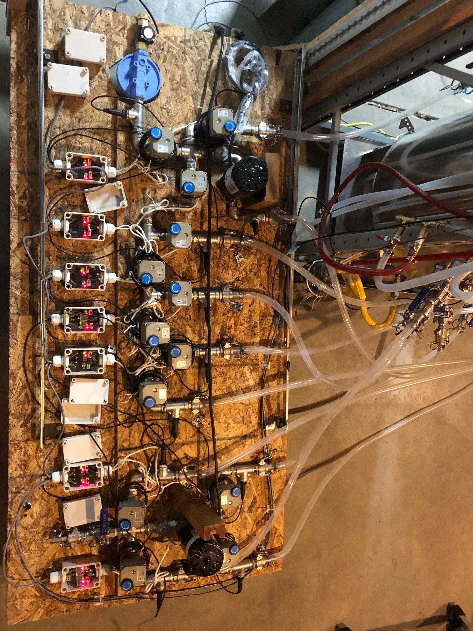
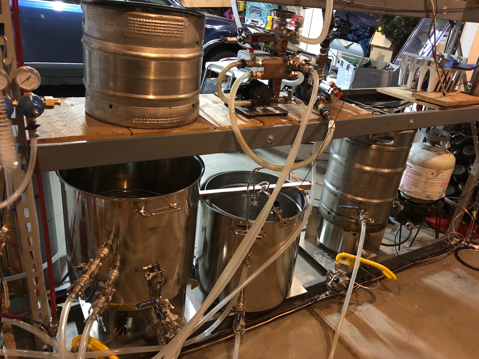
Here is the control panel - I got all the expansion SSR boards connected and I believe they are registered correctly in BrewBlox - though I can’t figure out how to identify which is which yet. (any ideas guys?).
Here is all the control ball valves with water filter and flow meter. All the temperature sensors are wired and register correctly in BrewBlox as well. I know support for the ball valves is next month I believe.
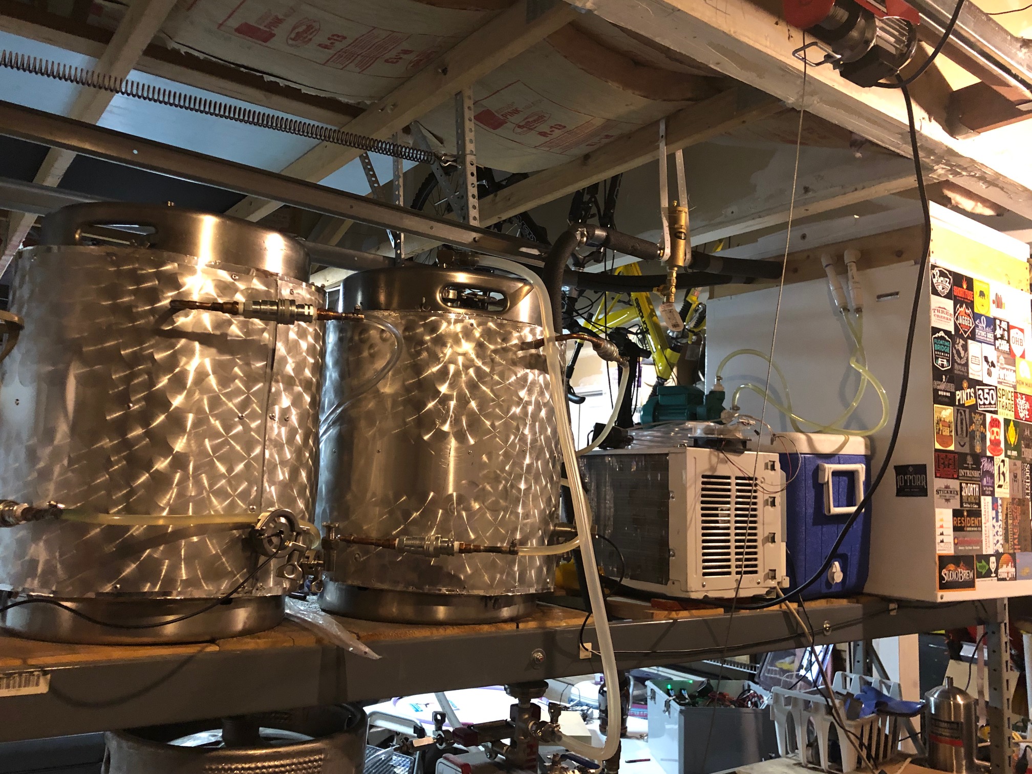
Here is some layout pictures as well.
I felt it was important to share what I have also, so you guys can see what I am trying to work with. I am NOT very savvy with the software setup and have a lot of Noob questions. I usually do well with bread crumbs for information and like to tinker from there.
For those of you that are more well versed in the Brewpi/Brewblox setup - please comment and reach out would love to learn and grow with all of you and this process. Open to any feedback, thoughts etc.
Thanks in advance.
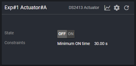
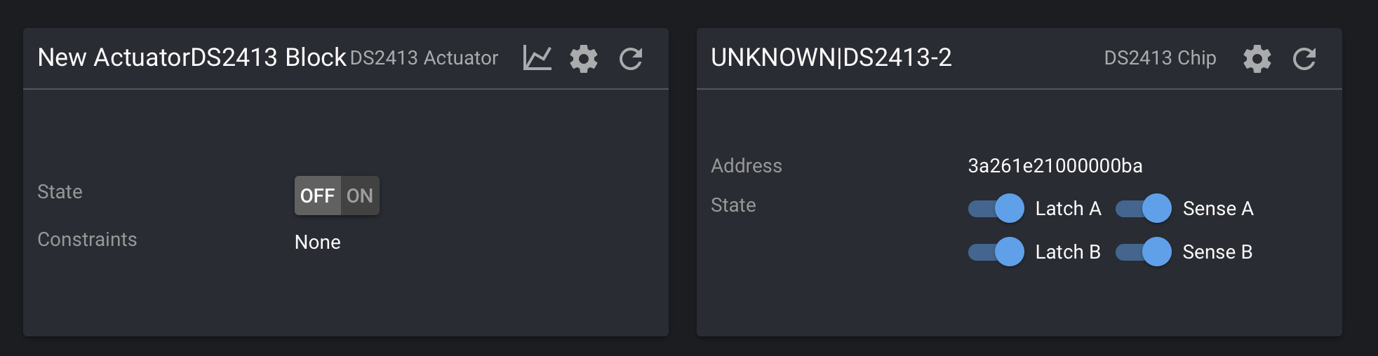
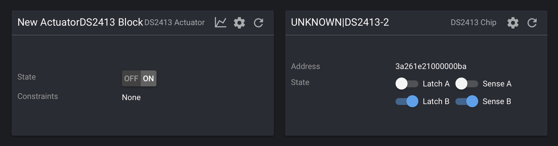
@cschmaltz to find out which expansion board is which just add a DS2143 Actuator assign one of the unknown SSR Boards and assign channel ‘A’. an click create.
Yes that helped - I’m pretty sure the other issue is that my wiring is not 100% complete yet. So I was able to get the Expansion boards all wired up and recognized with the actuators that I am using all identified along with the RJ-12 cables working i.e. all green and red LEDs I have all my temperature sensors identified and labeled, all cables wired correctly there as well. I know support for the ball valves should be next month (March).
How do you save/backup your current configuration setup?
How do you get the blocks to move, I have tried several browsers and key combinations and it doesnt appear where I can move them yet, perhaps there is another trick?
You can move widgets in dashboards by clicking the “edit dashboard” button and dragging them around. You can’t move blocks on the service page (it’s a transient display of all blocks on the controller).
Brewblox-ctl has commands for exporting / importing your datastore. You can use the spark widget to create a savepoint (in the datastore) of the current blocks on the controller.
Ok - thank you -
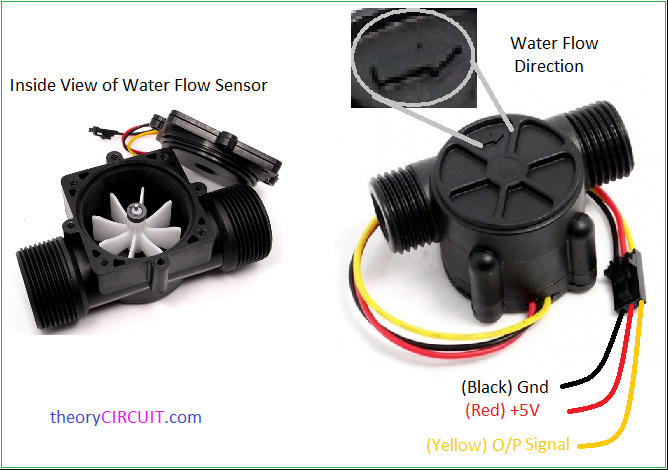
What block “type” would I select for a RJ12 connection for a flow meter that would use a python script to send “pulses” to help determine the amount of water entering the system? Water volume with flow meter
I need to get more of my wiring completed to do more testing with my relays before I can ask more questions. Sorry for the Noob ness.
RJ12 is a connector form factor, it doesn’t say anything about which signal is on each of the 6 pins.
You should never just plug in something you did not buy from us, just because the connector has the same shape.
One of the RJ12 pins has 12V on it, which is very likely to cause damage to incompatible electronics or the Spark.
The outer pins (1 and 6) are RS-485, which we can use to talk to extension boards that are not OneWire, if they speak the right protocol. The middle 4 pins are 12V, 5V, GND, OneWire.
Here is a higher res version of the file from the post I referenced earlier. I agree and understand the pin out portion, and it is currently that way. Same power requirements and pin outs. Instead of wiring it directly to the RPI, based on the diagram and equipment requirements the Spark will be able to provide it natively. Electrical Circuit - C.pdf (64.5 KB)
and
That flow meter is a simple pulse generator, for which you need to have an interrupt based microcontroller to listen to the pulses.
The BrewPi Spark will not support that. The way to support this would be to have an Arduino or similar small microcontroller act as a slave device with as only task to read this sensor and communicate with the Spark over RS-485.
The RS-485 communication has not been implemented yet, because all the expansion boards are currently OneWire. It was included in the hardware for future additions.
I will have to implement it soon for new IO modules, but currently the Spark has no way to add a sensor like this or even to talk to custom slave devices.
OK - no problem I do have an arduino lying around I can add too my setup - Ill have to research some more and ask questions about how to connect/wire it all together. I understand the software support part is pending, that is fine this isn’t a major item for the brew process to work, was a nice add-on.
Again, thank you so much for your time and support with such a huge endevour you have been able to support and take on - its quite impressive!
I now have all the expansion boards setup and labeled, in theory if I have a MIN time on and set it for XX - when I change the “State” from Off to On then the relay is activated and the device that it is connected too should turn on?
I just want to do a connectivity test for ea. of my outlets for the device they will be connected too. If this is or is not the correct process please let me know what I should have setup to have the same outcome. TIA
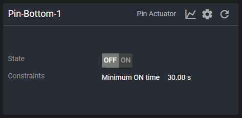
Also, is the process also the same for the “PIN” connections directly off of the spark for activating the relays?
Once this is tested, verified working, then I can move onto the ball valves when that support becomes available. Baby steps!


 I have all my temperature sensors identified and labeled, all cables wired correctly there as well. I know support for the ball valves should be next month (March).