Looks good. May want to run some comparable tests on upward slopes and cold crashing, but I’d say you’ve got your settings for the glycol cooler.
Yeah will do.
One of the difficulties I’ve encountered in setting up the test runs, is because of mutex etc its not straightforward to run a test because if you heat up to say 14 and then try and do a ramp down to 12 the mutex prevent the cooler coming on and then you’re always lagging behind. So what I’ve been doing is just getting up to start temp and then restarting the spark to reset the mutex, don’t know if there is an easier way of doign this?
Cheers
Joe
Rebooting the Spark is probably the most efficient way to go about it, but I assume you’ve been physically resetting or power cycling the Spark.
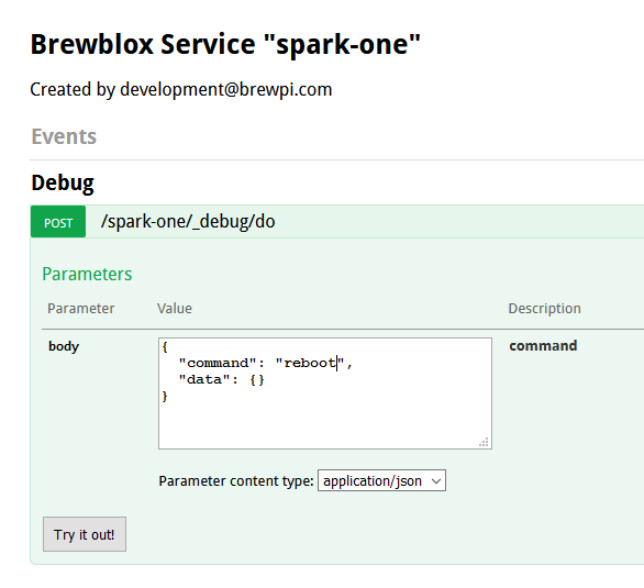
There already is an issue on the backlog on connecting the reboot command to the UI, but for now you can also run this command:
brewblox-ctl http post https://localhost/spark-one/_debug/do --data '{"command": "reboot", "data": {}}'
Don’t worry about the error: the controller never replies to the command, it just reboots.
Edit: you can also visit https://pi_address/spark-one/api/doc in your browser, expand the _debug/do command, and call with '{"command": "reboot", "data": {}} in the “body” field.
1 Like
Yep that’s what I’ve been doing!
Bob just trying to get my head fully around this statement so bear with me here.
The way i have calculated my minimum on time as i’ve been tweaking is as follows
- I have a pwm period of 10 minutes on the cool PWM
- This means I have six 10 minute periods in a hour in which to turn the cooling actuator on
- If I am to maintain a 1C/h slope down this means that for each period I need to achieve 0.16 drop in temperature from that which i started pre the actuator turning on the ball valve to allow glycol to flow to the fermenter (1oC / 6 periods) = 0.166… oC
- So what i did was tweak the minimum on time and watched the starting temperature before the actuator was turned on and kept tweaking the value until i got an ending stable temperature drop of 0.1666…oC as a result of each period. This seems to have worked out pretty well and i’ve arrived at a minimum on time of 35 seconds to achieve this drop!
- I adjusted the Kp value on the cooling pid so that the actuator turned on at the same point i.e 10 minutes after the end of the last period (this is where im beginning to doubt myself). It appeared that as i raised the Kp value (made it more negative) that this narrowed the error in delay between each subsequent period starting, some times it would be almost bang on 10 minutes other times it would be closer to 14 minutes depending on the changes I made to the Kp value or thats what it appeared to me, there may be something else at play here that im not understanding (again i may be talking absolute rubbish here).
I seem to have got good results with tweaking the minimum on time but im not clear on the relationship between the pid controller values.(I’ve read the wikipedia link but none the wiser in terms of its application to brewblox) and how they should be utilized to tighten my cooling.
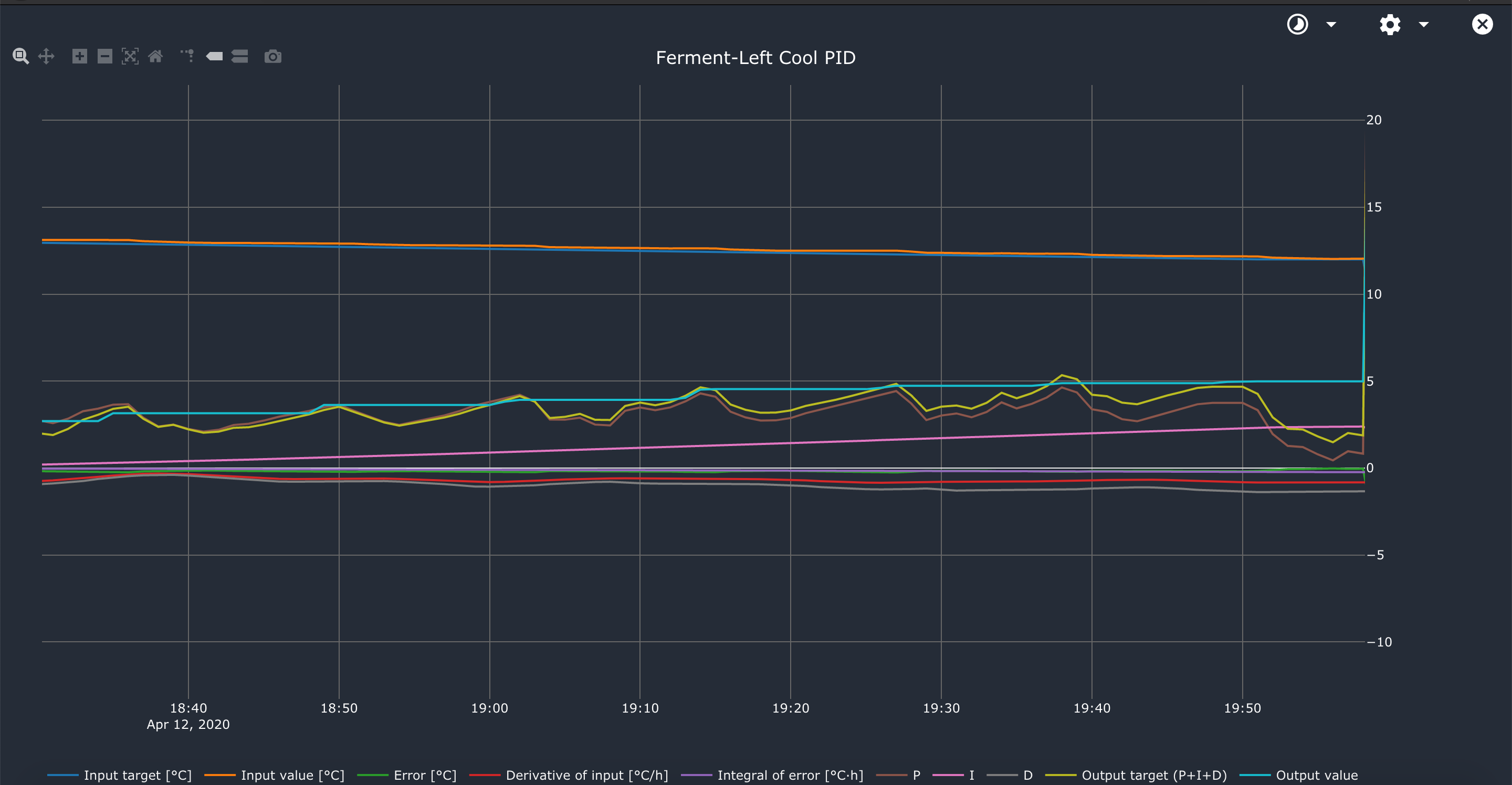
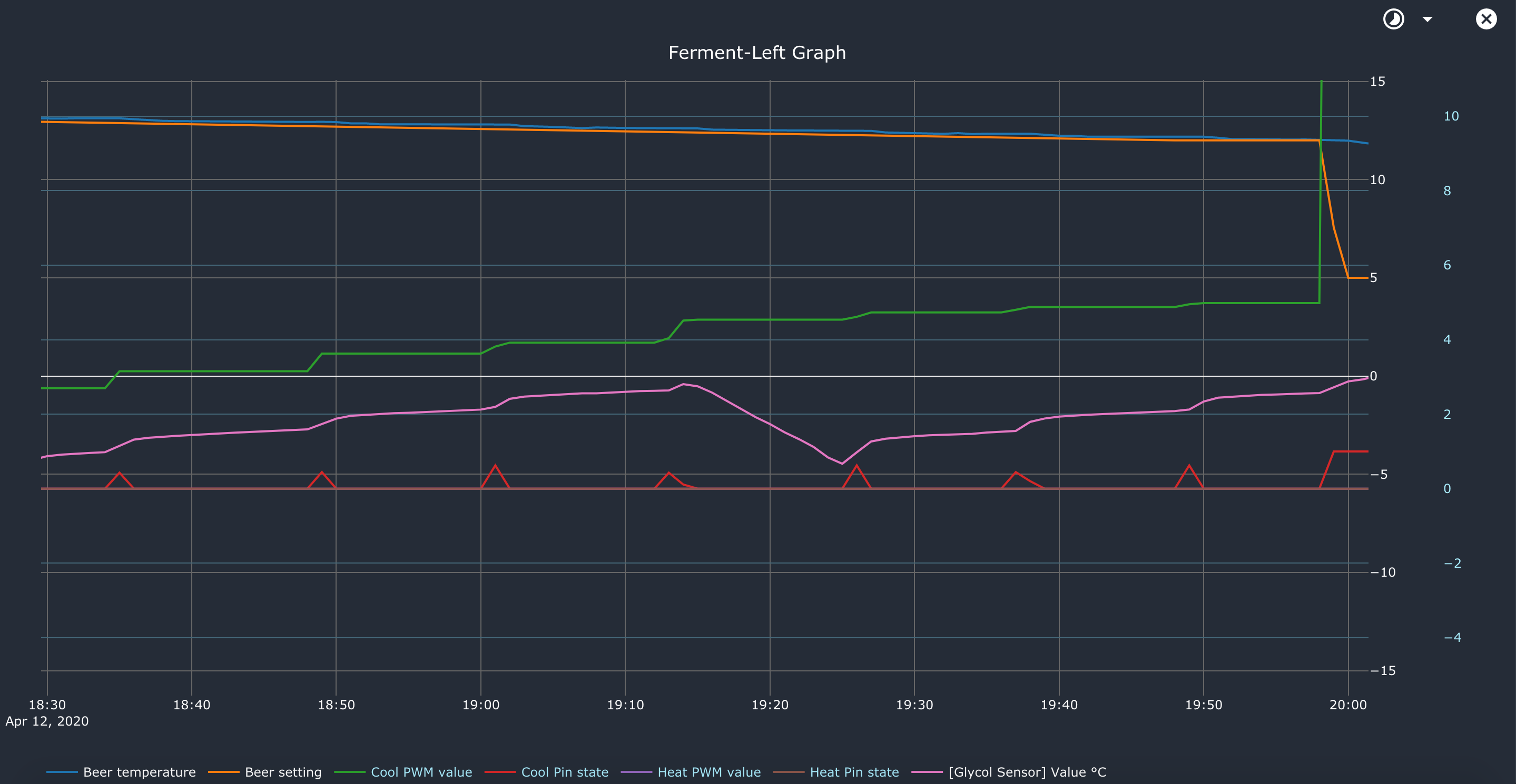
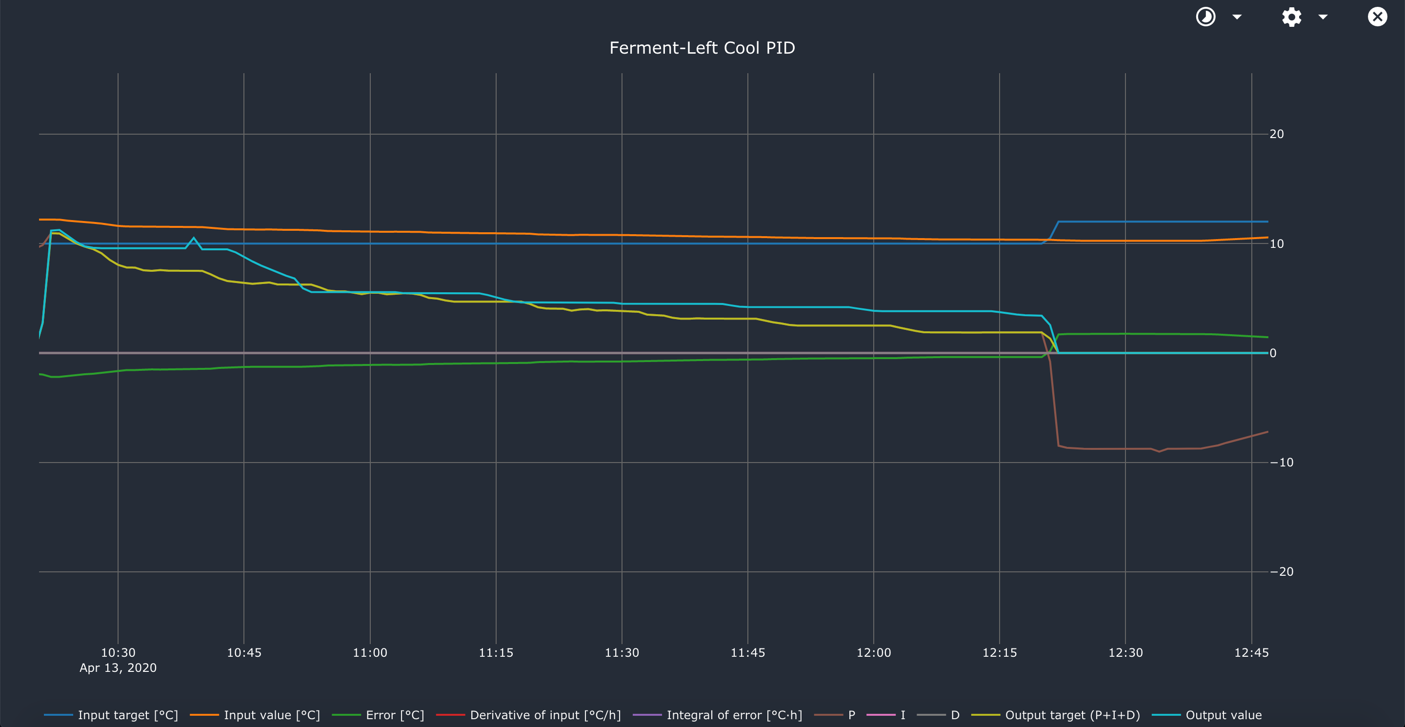
For info the temperature started to drift towards the end of the ramp down to 12oc and the integrator also started to rise graphs below of these hence why im coming back to you after the positive results for the majority of the ramp down test.
brewblox-blocks-spark-one(1).json (10.1 KB)
When PWM value should be only 5%, but your minimum cool time is 10% of the period, it will start to lengthen the period to still reach the desired value under the constraints.
So don’t make Kp too low. The proportional part should do most of the work.
The integrator is for correcting small steady state errors, the derivative to counteract overshoot.
The bulk of the work should be done by P.
If Kp is too low, you’ll go to the setpoint slower than you could. This gives the integrator time to increase. By design, the integrator is slow to increase, but also slow to decrease. So a too low Kp can cause overshoot actually. Because it forces the integrator to do work the P part should do.
Look at the PID graph to see the P, I and D parts to get a feel for it.
So to summarize: you want Kp high as possible, for a responsive system. Just not so high it causes you to fly past your target all the time.
Keep increasing Kp until you are getting too much overshoot.
But, if you add some Td (about as long as the duration of the overshoot), you might be able to use a higher Kp.
So tune Kp first, without Ti or Td increase it until you get just a small bit of overshoot on a step.
The increase Td a bit so you don’t have overshoot.
Finally add some Ti, at about 3x the response time of the system to correct steady state errors.
You should not use a slow ramp to tune the PID. You should use square steps.
1 Like
What do you mean by square steps?
Ok cool so I’m ok with keeping the minimum on time though yes?
Elco already added advice on how to tune a PID.
For a different explanation of how and why PID settings interact, see: https://www.csimn.com/CSI_pages/PIDforDummies.html
A slow ramp and a flat line are very similar. It’s steady state. The temp is at the desired value, so the proportional part is zero.
Only the integral will be active if the process needs some cooling to stay at the setpoint.
To tune Kp, you need to start at the wrong value and approach the setting, hence a step.
Minimum on time sounds fine.
1 Like
Hi Elco
Apologies you’ve got me a bit confused now with these statements
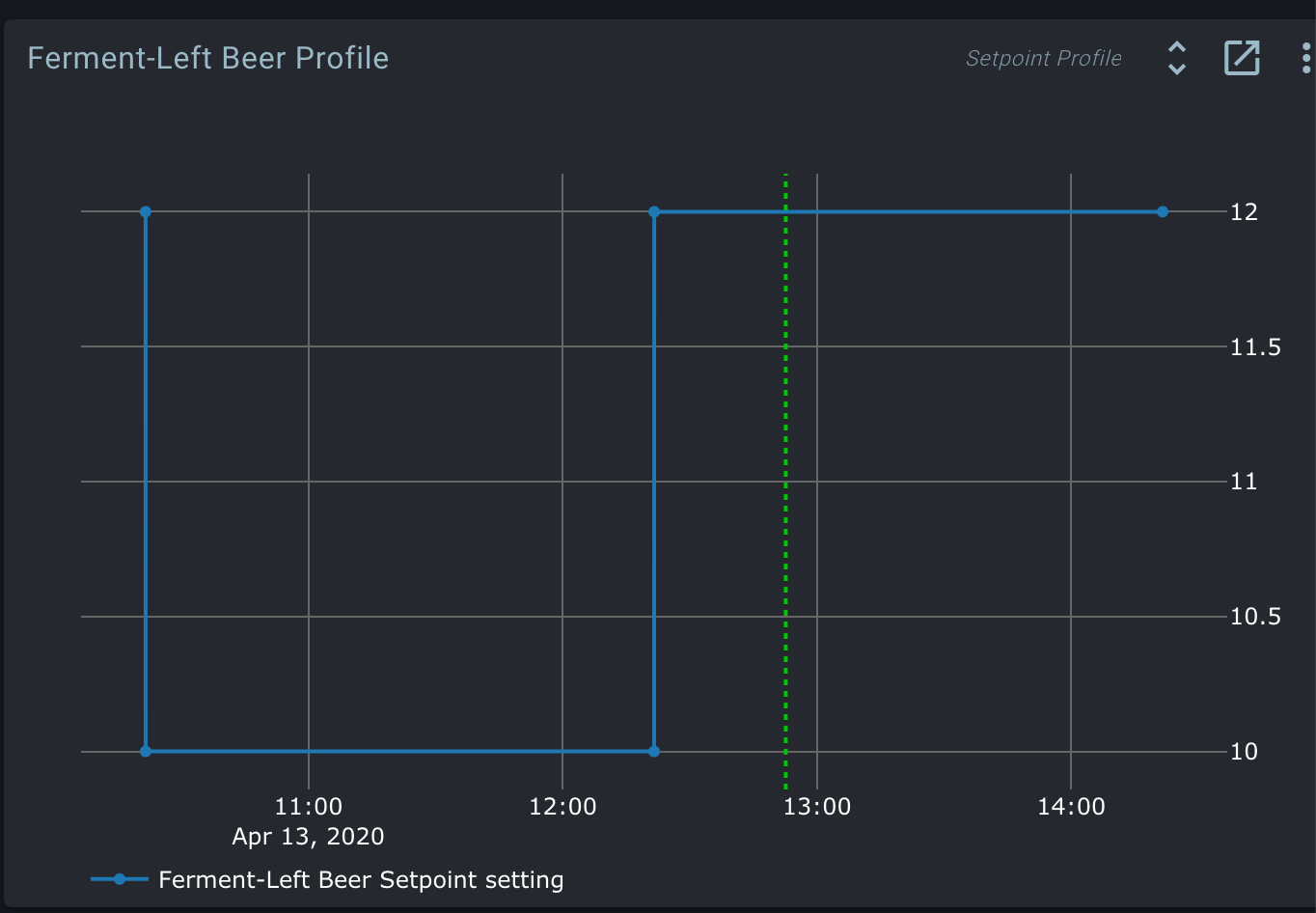
I had been following a test profile recommended by Bob, to me this is starting with the wrong value and approaching it, are you suggesting something different?
Below is the profile Bob had suggested!
I know that’s what Bob suggested. It’s okay to test how well the setup works in normal situations, but it is not the best profile to get good feedback on PID tuning.
To tune the PID, you want a profile that triggers all 3 parts:
- A step 2 by degrees, for the proportional part
- Then holding that temperature to check/adjust overshoot
- Hold that temperature long enough to reach steady state (2-3 hours?)
Tracking a ramp doesn’t require a well tuned Kp, because it is mostly the I part that is active. It was a good test to tune the minimum ON time though.
In other words: the first part of the test I sent you is now done. Your PWM/actuator settings are good, and it’s time to fine-tune your PID settings.
In terms of profiles, the test Elco described is:
t=0, setpoint = X degC (current temp, doesn’t matter too much what, as long as it’s not too cold)
t=1s, setpoint = X - 2 degC
t=2h, setpoint = X - 2 degC (give the system time to reach)
t=2h1s, setpoint = X degC (go back up again)
t=4h, setpoint = X degC (give system time to reach)
1 Like
Ok
So ran test with Kp set to -5 results attached.
I’m guessing Kp not enough? needs to be -10 to -30 at least as a starting point?
Cheers
Joe
… why? You already knew from earlier testing that -5 is way too little. You also don’t need me to tell you that right now your temperature is sauntering vaguely downwards.
Yep but i was going on what Elcos settings were that i’ve seen him post, as i thought the previous test we ran wasnt good for tuning Kp so i started with the settings Elco used as a starting point 
Re running now with -20 as the starting point and its dropped initially 1.2oc in 8 minutes so looking more promising!
Sounds good. The next important point for tuning is what happens when it approaches/reaches setpoint. Check the PID graph at that point, and you can see the interaction between settings.
1 Like
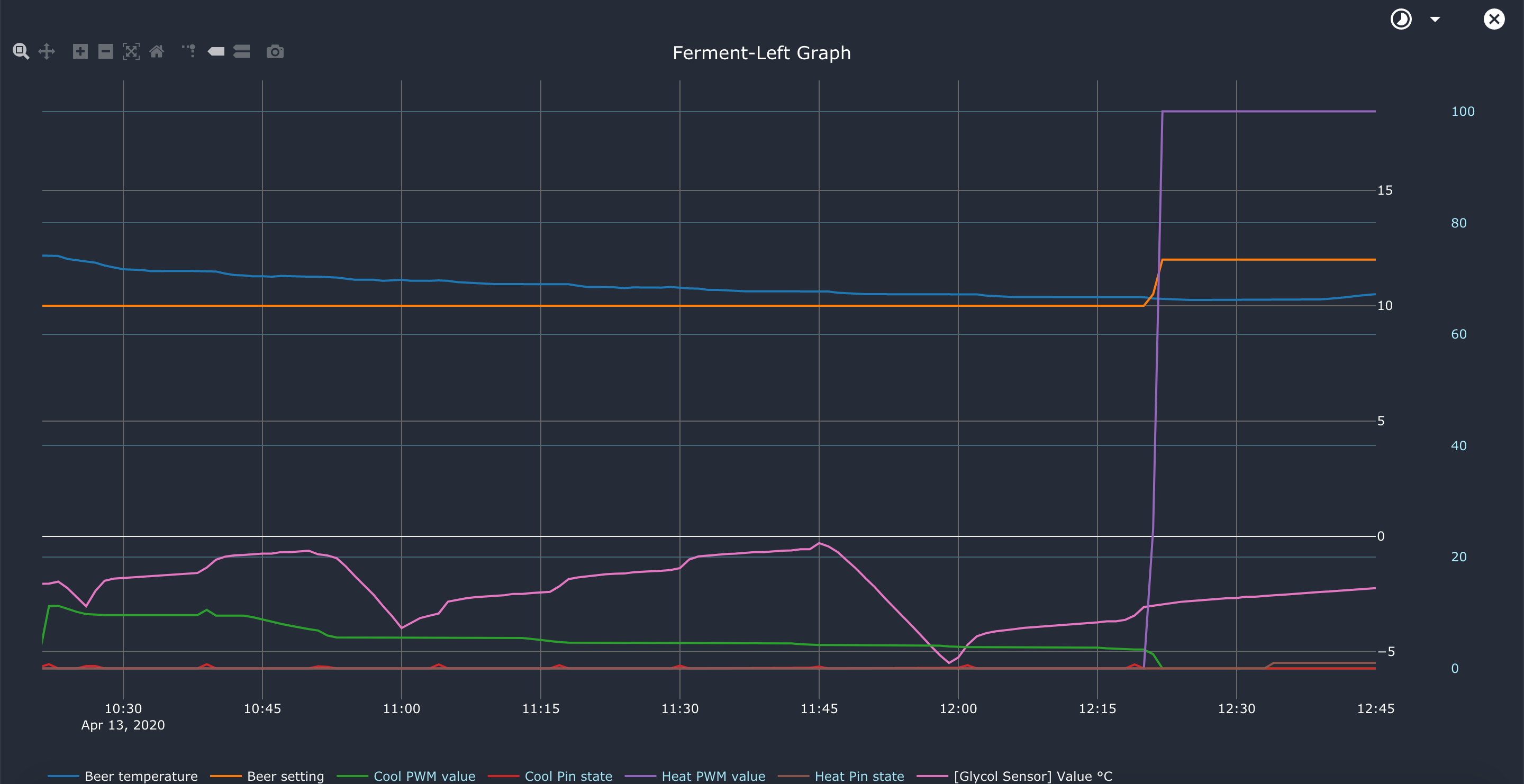
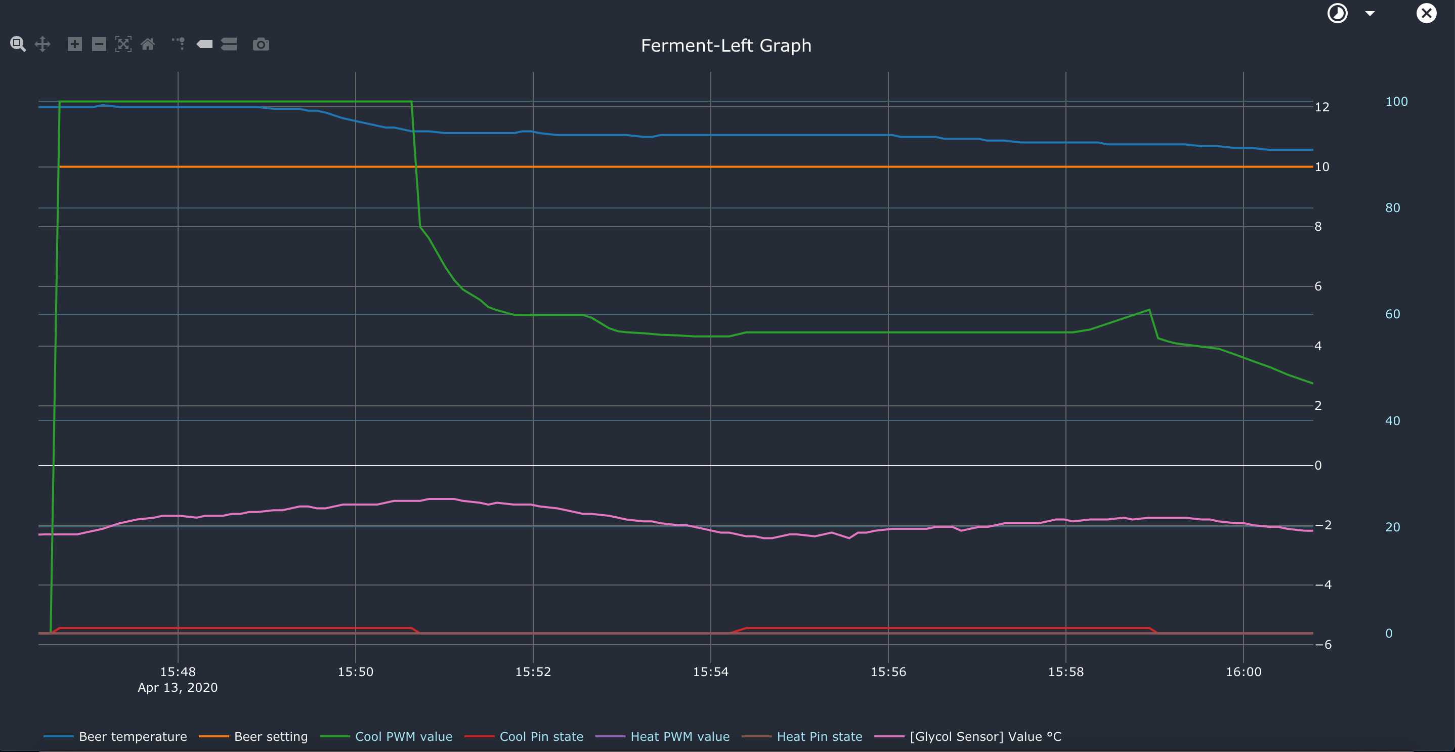
Looking like Kp -60 to -65 to get it to keep the cooling on to reach 10oc with .06 overshoot before the cooling switches off over 14 minutes to get to that temp.
Bob
should I expect to see a cut out of the cooling like there is at approaching 15:51 and then back on at 15:54 or am i looking for the cooling to remain on the whole time until it reaches target?
Cheers
Joe
Cooling should taper down before reaching the setpoint, to avoid overshoot.
1 Like