Trying to set up Spark 4 with 4 GPIO modules and RPi 4 Model B/4GB. All 4 One-Wire probes on 1st module are reading correctly and controlling SSRs correctly. Module 2 is reading about 200 degrees F above ambient temperature on all 4 slots. I have tried one at a time in different slots and trying the same probes on module 3 and have determined that the same probe will read correctly on module 3 while readding 200F over when hooked up to module 2. It’s worth noting that I am extending all probes by using CAT6 line using only 3 wires. I have re-crimped all lines found to be faulty and am confident that the crimps are correct. They are all on average extended to around 100 feet. Length of cable does not correlate with malfunction. My power source is external (12VDC; 12.A; 300W) and I have verified that all modules are set to external. The DC power inverter is plugged into an outlet in the wall and have not determined if anything else is affecting voltage. See the log run below and that you in advance for your help. Also is there a guide to reading these logs and error messages contained therein. I would like to be able to troubleshoot issues on a deeper level.
Does the problem reproduce for module position 3, or that specific module (hardware)?
Modules are indentified entirely by position: if you swap modules, all settings remain valid.
For this specific issue, logs don’t contain much relevant information, as they can only get so much information from the controller. I do see quite a few controller reconnects. I assume this is you plugging/unplugging/power cycling the controller?
If you’re still interested in the mostly service-side feedback provided by logs, I can write a short primer on it.
Good suggestion. I will try this tomorrow and post my experience. I imagine if module 2 is put into position 3 and continues to have issues we would be getting closer to being able to conclude that this is a hardware and not software issue?
Yes, I have been cycling off and on to troubleshoot.
And yes, it would be nice to have a primer. I would much rather troubleshoot myself before taking up your time.
I didn’t spot this earlier, but both your spark-one and aquabrew services are connected to the same controller. This typically causes problems.
While aquabrew has a --device-id set, spark-one does not. This is equivalent to a wildcard.
If you only have the one spark, you can safely remove spark-one by running brewblox-ctl service remove spark-one.
Primer is published at Analyzing log output | Brewblox. It’ll be available on brewblox.com / brewblox.netlify.app after the next release. Please let me know if anything is unclear or missing.
I am not sure if this is related but when I went to look into things today I noticed the Spark 4 did not connect to Brewblox. After examining the Spark I found that there was no IP address in the top left and the OK and Reset buttons were blinking green. I tried to reset and re-provision but I could never get the lights to flash blue. I thought maybe the wifi was out of range so I moved it directly next to the router but still got no IP address and no signal. The spark seems to be controling the fermenters still and I was able to ssh into the Pi in order to remove spark-one.
If it makes it more reliable, I’d rather just hard wire the Spark into the Pi via ethernet and was wondering if it was still possible to connect them via ethernet after already setting up communication via wifi.
The spark should prefer ethernet connections over Wifi, but I’m a bit hazy on what behavior is live, and what is part of a networking fix that’s currently in progress.
My apologies, scratch that last remark. The printer on the same wifi network was acting up and I realized this was a network issue unrelated to the Pi or Spark.
I was able to remove the spark-one and confirmed that it was removed by viewing that it was not an option under services on the UI. Nothing seemed to change after this.
I then rearranged the modules from the following: 1, 2, 3, 4 to now 1, 3, 4, 2. 1 and 3 are still working while 2 and 4 are not working.
Then switched from 1, 3, 4, 2 to 2, 4, 1, 3 to see if anything changed. 2 is now reading on all ports but ~200F over, 4 is not reading, 1 and 3 are reading correctly still.
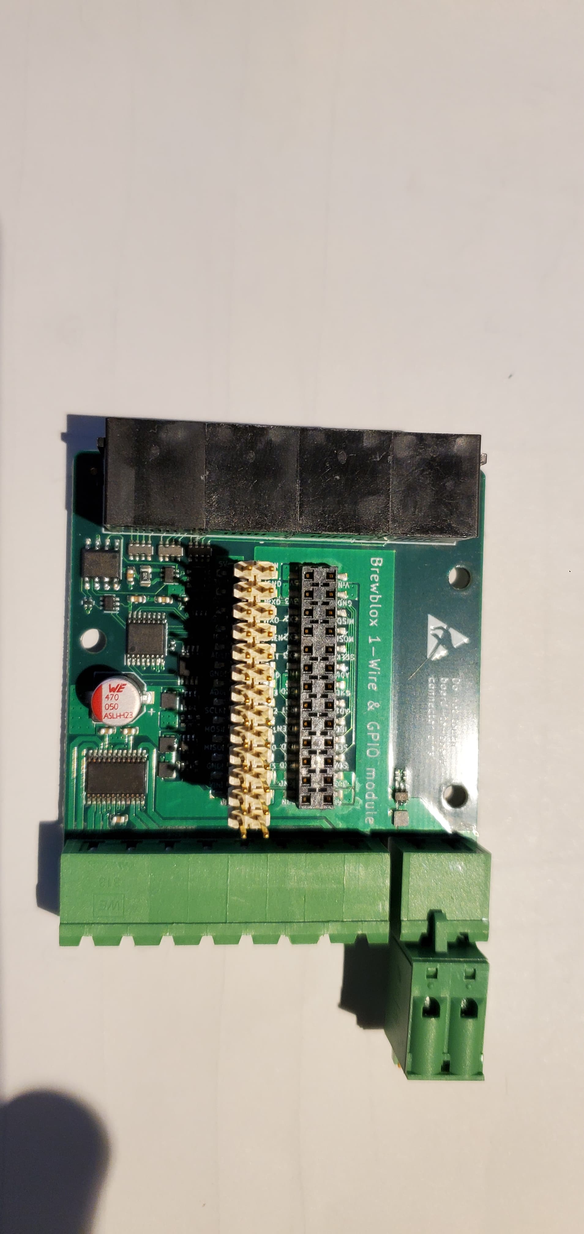
I’ve seen that you like pictures of the inside of the modules, please see below:
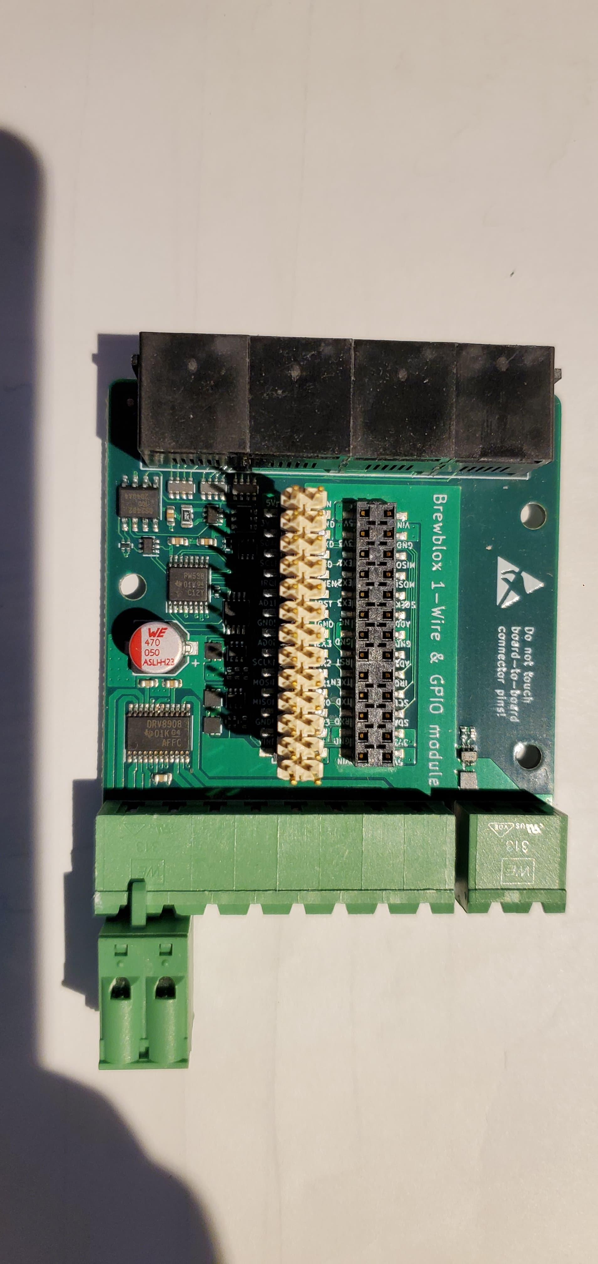
The 1-Wire pin DS2424 on board 2 looks like it has a bit of a blob under the pin, but might be nothing. Hard to judge from the photo.
Did you have them wired wrong when you initially connected them? I don’t think it should do damage on this new IO module, but I am not entirely sure.
100 feet of cable is very long for OneWire. Have you tested the module with short sensors?
Setting the modules to external power has no effect on the 1-wire part of the board, it switches the IO voltage of the green terminals to 12V.
The first time I tested to see if extension would be possible, I mismatched the wires until I understood which ones needed to be where, but I did not note which module I used to do this test. However, once I got the pins right it read the probe correctly.
I tested with a one-wire temp sensor from the BrewPi store that I confirmed was working and all of those that are working now are being read from around 100 feet.
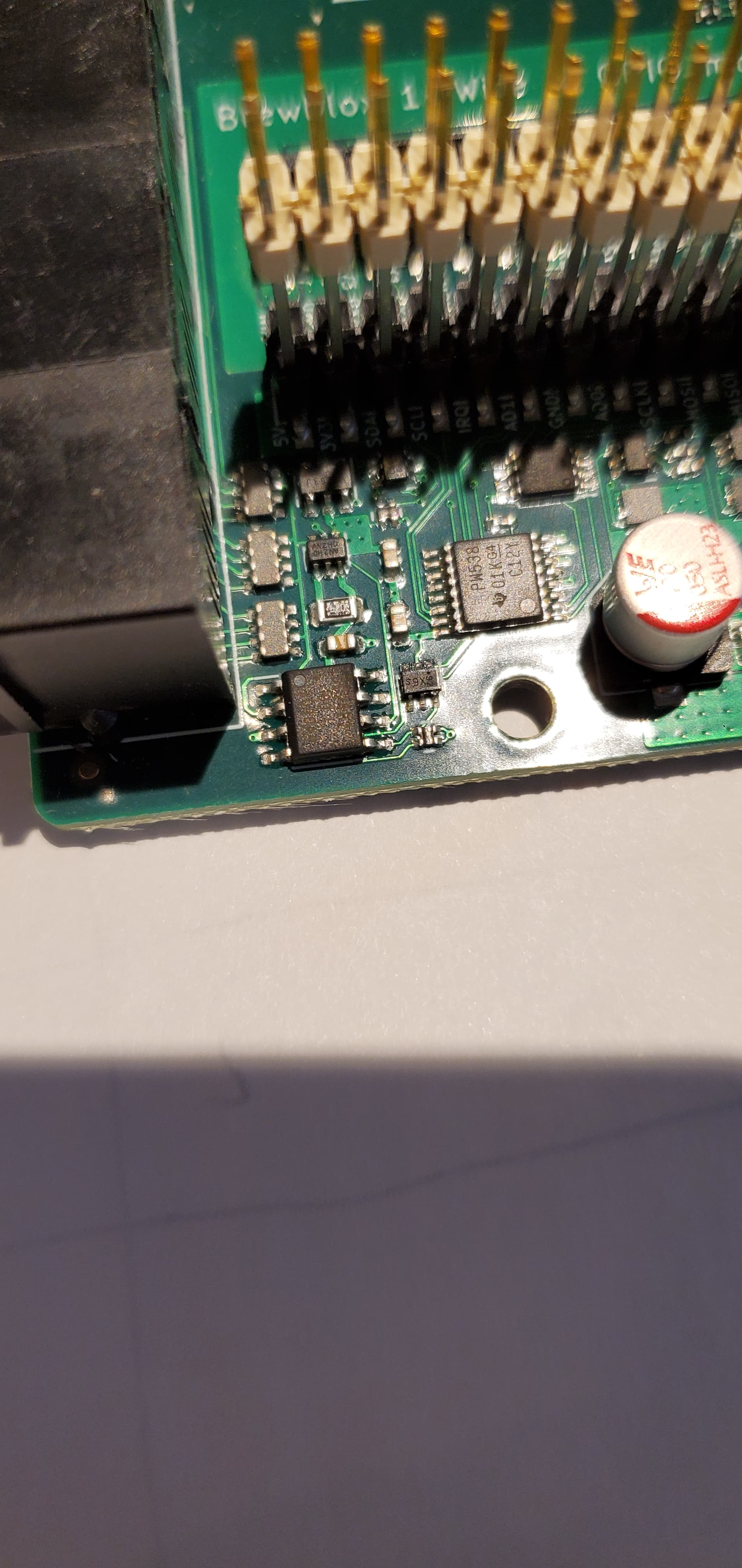
If you point me in the right direction of the 1-Wire pin DS2424 I can try to zoom in on for closer inspection.
On the first photo, top left. 3rd pin from the left was suspicious I think.
This wouldn’t have an effect on other modules though I think.
This is the best my phone will do.
Is it possible that the cumulative length of the 1-Wires together would cause an issue?
After some reading, I found this. Since fermentation does not deal with rapidly changing fluctuations, would it then be possible to read one probe at a time to allow for a longer one-wire network?
Switched Networks
To allow networks to grow in complexity without growing in weight and radius, the network is divided into sections that are electronically switched on one at a time. Using low-impedance, single-supply analog switches, the network can physically resemble one topology, but electrically resemble another. This means that a star configuration with a switch on each branch would actually resemble a linear topology. In this case, only one branch is active at any time.
The example above appears like a star topology network with a radius of 150m and a weight of 450m. However, when each switched path is considered individually, the network is actually a linear topology and the weight is only 150m.
Alternatively, if I connected the GPIO Modules via ribbon cable or something similar in order to reduce the one-wire cable lengths would this solve the problem?
On Discord, somebody else just happened to post his Arduino OneWire slave. It’s not something we can sell, but it may be useful as relay station for OneWire sensors.
No, SPI and I2C are not suitable at all for long cables.
Why are you extending the sensor cables instead of placing the Spark much closer to the tank? I would opt for multiple Sparks instead of very long sensor cables. They can all connect to the same server and be shown in the same UI.
With passive power over ethernet, you can run a network cable to provide both network and power to each Spark.