I still have to add the valve boards to BrewBlox, they won’t show up yet.
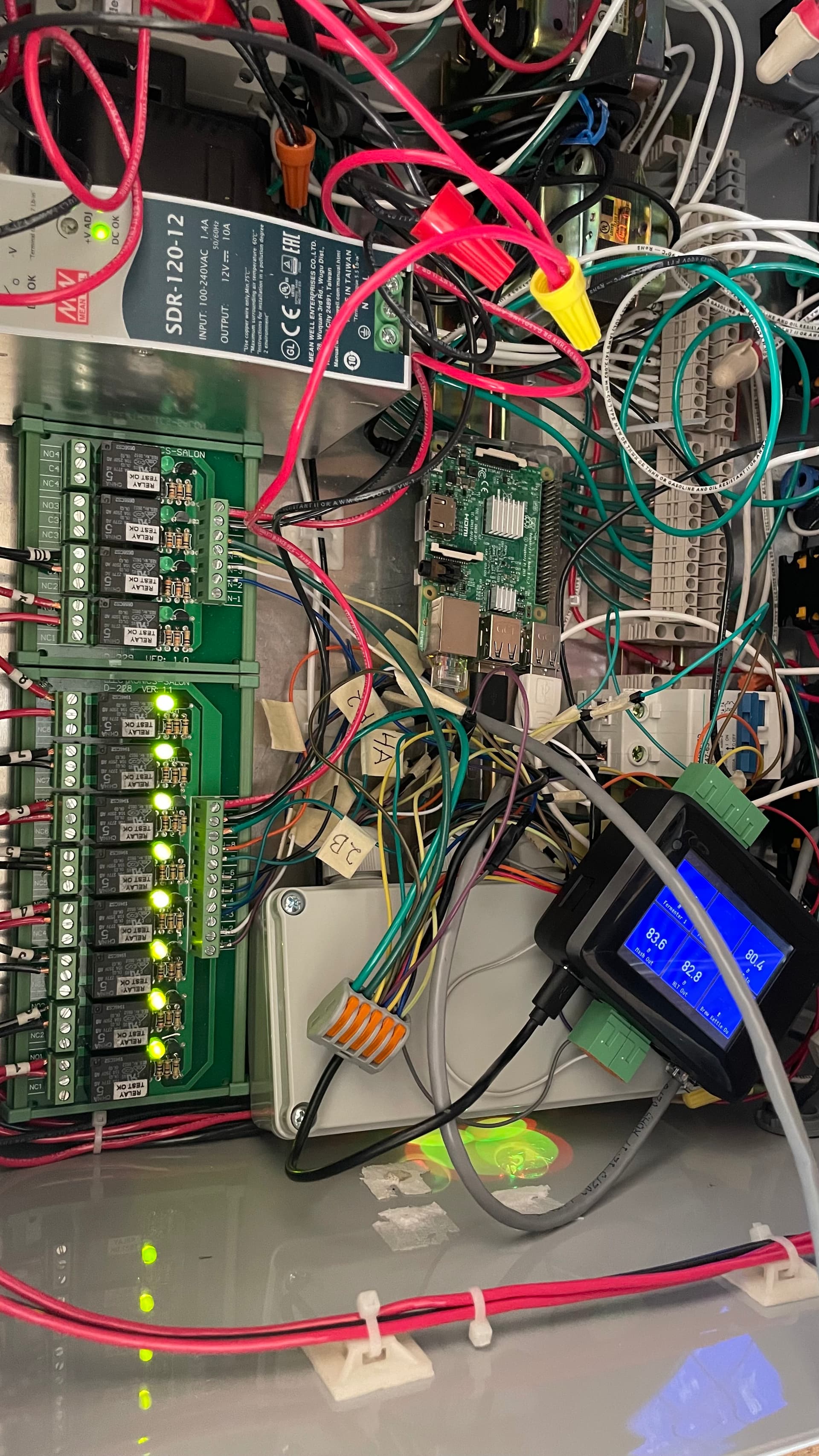
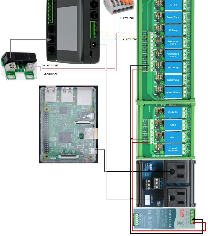
@elco I understand the SSR expansion boards aren’t setup yet for Brewblox that is fine - my current inquiry is try to ensure or verify whether or not the current wiring (prep work) is correct for the SSR’s. So In this picture I am basically showing that I got 1 of the displays to show up on the spark (intentional there is only 1 currently). The cable wiring is correct cause it powers on the additional SSRs as you can see with the green LEDs. Currently there are 3x single wires (red, green & yellow) ran from the spark to the SSR boards the rest are NOT connected in the picture but were before (color matching ends). Basically only the + (purple circles) side is connected and based on the previous posts that i referred to I wanted to know where the - (green arrow) part of the cable should connect too.

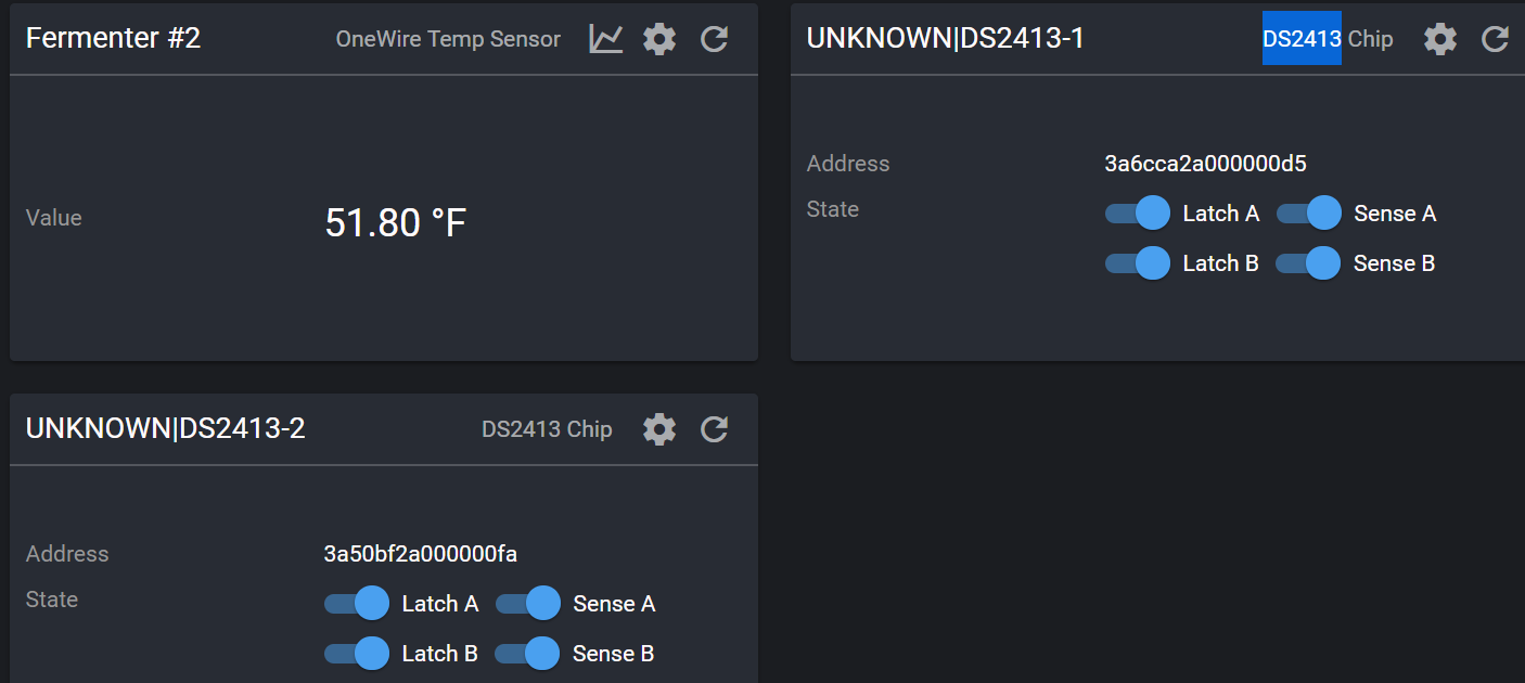
Because, currently the spark recognizes 2x DS2413 chips, I am assuming these are the larger boards, not the expansion ones from you store, that I have connected over the RJ12 cables.
Here is the relay board with some labels also for reference.
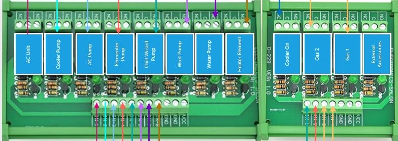
Currently the NO & C are wired but there is nothing on NC currently and that is where i theorize it should be connected too.
Thanks in advance, I hope this is enough info for what I am asking.
So I think the 2413’s are the SSR expansion boards cause I fixed my cable for them now all 4x show up on the “service page”. Otherwise I do like the interface very much and obviously a lot of work has gone into it and it shows and we really do appreciate all the work you guys have done on this. I’m sure there will continue to be questions and inquiries as we go forward, but so far I am pleased. Any thoughts on the wiring portion? Where would python scripts go for brewblox for it to get readings from? what type of device would you categorize a flow meter as? TIA @elco and team!
Hi Elco,
When do you schedule to add the SSR Expansion board to BrewBlox. I am currently controlling my fridge using 2 SSR, the expansion board connected to my Spark One V2 and Brewpi, but would prefer to use BrewBlox.
Cheers Ken
It is already supported.
Ok so I was able to FINALLY! wire my SSR relay boards. the 8x port all the lights have power from the 4x expansion boards and all the lights are illuminated on the relay board. but for the connectors that come out of the BrewPi they do NOT illuminate the lights on the board.
I have tested and verified the wiring is correct, and the board is also functional. I am not sure why or what would cause there to not be enough power from the green/orange power connectors off the Brewpi to not work but out of the RJ12 ports it works just fine… @Elco any thoughts or suggestions?
Can you share how you have connected things?
Did you measure anything? I don’t have much to go on here.
the grey box has the 4x SSR expansion boards. I have a video too that shows that the 4x relay board gets power when booting up but the lights dont stay on after. All the + wires go the the INx on the relay board and the - goes to the GND on the board and those wires are separated by groups of 2 from the expansion boards and from the Brewpi itself also. Then the ground GREEN wires go to ea. relay board.
Measure… um there is 12V coming off the transformer from 110 to 12v and there is 5v off of ea. terminal - 4.33V on the relay for the ones lit up. 0v on the other.
There is 1.38 coming off the Brewpi pins with the green/orange adapter no wires connected (on that port).
The Power supply is a 5V DC 2.5 Amp - which looks like is the Req. power
Please draw a schematic.
Ok it will be a few days for me to update the Visio drawing but will do
It doesn’t need to be pretty, a simple paper drawing would suffice. I’m just not going to decipher what goes where from a photo.
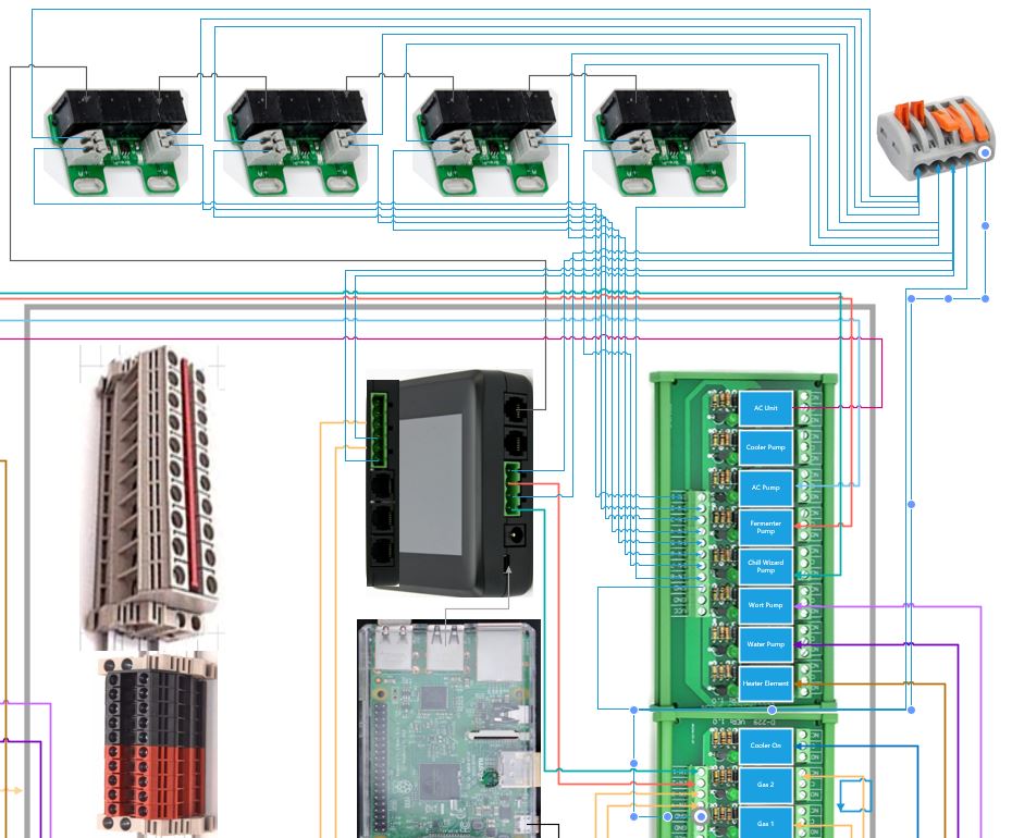
here is a rudimentary version.
All the grounds/negative from the expansion board go to the terminal connector. The + Pos go to the Input on the relays. Between the 2 pictures this should help - i hope.
After the replacement power supplies show up Monday will revisit and test then.
** OK New PS showed up and installed ** still not sure how to better troubleshoot the under voltage issues
ok @Elco from your last comment/update from:
So as I understand: The - terminal on the SSR ex. board, should go to the INx (input) on the 8&4x Relay board.
When you say connect the GND from the Spark to the relay board, you are referring to the green connectors, on the spark correct? cause the actual power supply(s) for Spark & RPI are 110V off of a “ASI IMACP02 Duplex Three Prong Modular Outlet, AC Receptacle, Din Rail Outlet”
Both Relay Boards get power from a: " Mean Well SDR-120-12 DIN-Rail Switching Power Supply, 12VDC, 10A, 120W" - all amazon items. That are wire nut split power and both boards have 12V of power. so they do get the correct amount of juice.
So power goes to the VCC on the relay boards. and the + terminal from both the SSR exp. boards go to the INx - BUT you’re saying to move them to the - Terminal and I shouldn’t need a 2nd wire at all or?
What about the green terminal adapters on the spark, saying only 1 wire? Cause initially my relay boards were buzzing/chattering when I didn’t have them grounded so Im trying to figure out how do I complete the circuit.
Sorry Elco I am trying to process and understand.
@Elco ok so I tried to consolidate the connections here with labels based on what I understand with the +/- terminals and how you suggested to connect it. What I am unsure about is the GND for the relay boards. Obviously this just shows a single connection with the data cable and with the connectors from the Spark.
Currently if the data cable and the exp. boards are connected the relay board lights up, but when I have the connectors off the Spark connected they don’t light up UNLESS i disconnect the data cable. I can’t seem to get both to light up at the same time.
Based on the schematic for the relay boards they are NPN - so im hoping this drawing will help. This drawing is what i would consider reverse/backwards to how it was originally wired, meaning the + terminal went to the input and the - terminal went to the GND.
I hope with all the pics/info I have provided is helpful enough, if you need more please let me know. I’m just trying to figure out what the next/best step is to continue fwd.
The + terminal of the SSR board should not be connected. You are now connecting 5V (+ of the SSR board) to 0V directly (green connector -).
If you have the relay board connected to the green terminal -, it is connected to GND of the spark. The GND of the SSR board is also connected to the GND of the spark through the RJ12 cable.
ok so the green terminals on the Spark, should I also just be using the - terminal and not the + terminal, therefore both the green terminal & the SSR Board are just using the - terminal connecting to the relay board? is that correct or no?
No. You have the Spark green terminal that toggles between 0V/0V and 0V/5V.
And you have the SSR board that toggles between 5V/5V and 0V/5V.
So for the green outputs you will connect both.
For the SSR you only connect the -. It will get the ground reference through the RJ 12 cable.
SSR board and relay board have the same ground level through the path SSR board → RJ12 → Spark → green terminal → relay board.
ok got the ref for the SSR Board only using the - terminal, check.
the Spark - terminal would connect to GND on the relay board that the + lead connects to as well. (or maybe it doesnt matter?).
@Elco So for the GND can both relay boards have the same shared GND then? I’m gonna move things around wire wise and test. Hopefully you will still be around to help with the clarification.
THANK YOU!!
Ok wired as you suggested: The SSR board uses the - terminal, to connect to the relay board. The green terminals still do NOT light up the relay board and the + goes to the relay board and the - to the GND which is shared across both relay boards. Please correct me if i did something wrong or missed something. thanks.
NO! The reference (GND) comes through the RJ12. The - on the grey connectors is the signal that toggles.
Do you measure 5V if you have nothing connected to the Spark and a digital actuator turned ON? You might have blown up the outputs by connecting them wrong.
ok so the - on the grey terminals, single wire goes to the relay boards.
The relays that do light up have 3.24V using just the data cable.
I have not gotten to a point on the dashboard of building or loading anything so im not sure about turning on (how to) 1-5 of the digital actuators. I don’t think they have blown up cause when i turn power on to the control panel all the lights for both relay boards light up. and during the process of troubleshooting an wiring all this stuff they have turned on.
*ill upload some pictures but based on the new wiring directions. Power basically toggles between the spark actuators for the relays or the data cable to the expansion boards. The exp. boards don’t have the little red lights on them except 1x which you will see in the picture. And ill post the current Volt on the relays. Hopefully this will help and we can further troubleshoot what I need to fix. I also am working on updating the Visio drawing for you, so you can see the wire layout for the valves etc. I’m pretty sure i will have to start a diff post for the setup builder wizard just to make sure im tracking but at least I will have it all documented for easy reference. Also working on the remote access part to see if maybe that might be more helpful as well.