Please unplug and reconnect USB and power, and then reconnect them and run lsusb to check whether the Spark is detected as USB device. For more info, see Troubleshooting | Brewblox
pi@raspberrypi:~/brewblox $ lsusb
Bus 001 Device 005: ID 04d8:f723 Microchip Technology, Inc.
Bus 001 Device 007: ID 2b04:c008
Bus 001 Device 003: ID 0424:ec00 Standard Microsystems Corp. SMSC9512/9514 Fast Ethernet Adapter
Bus 001 Device 002: ID 0424:9514 Standard Microsystems Corp. SMC9514 Hub
Bus 001 Device 001: ID 1d6b:0002 Linux Foundation 2.0 root hub
** tried diff cable** Good to go now as fas as showing up in the cmd
Is it recognized if you use a different USB cable? It’s rather weird if your current one suddenly decides to stop working, but not unheard of.
showing up now with diff cable - but no change in the GUI or on the screen.
pi@raspberrypi:~/brewblox $ brewblox-ctl discover-spark
INFO Discovering devices…
INFO USB 3f0026000851353532343835 P1
INFO Done!
You still have to flash the bootloader.
I did earlier but im running it again right now:
pi@raspberrypi:~/brewblox $ brewblox-ctl particle -c flash-bootloader
Please connect a single Spark over USB, and press ENTER
INFO Starting Particle image…
INFO Type ‘exit’ and press enter to exit the shell
edge: Pulling from brewblox/firmware-flasher
Digest: sha256:1c481e82d0dd89f4a8b80ae0408000ccf381228bf7fdfb5366d85dbd8c55521c
Status: Image is up to date for brewblox/firmware-flasher:edge
Flashing P1 bootloader…
Error writing firmware: Timed out waiting for initial response from device
Command ‘docker run -it --rm --privileged -v /dev:/dev --pull always brewblox/firmware-flasher:edge flash-bootloader’ returned non-zero exit status 1.
running it 2nd time:
pi@raspberrypi:~/brewblox $ brewblox-ctl particle -c flash-bootloader
Please connect a single Spark over USB, and press ENTER
INFO Starting Particle image…
INFO Type ‘exit’ and press enter to exit the shell
edge: Pulling from brewblox/firmware-flasher
Digest: sha256:1c481e82d0dd89f4a8b80ae0408000ccf381228bf7fdfb5366d85dbd8c55521c
Status: Image is up to date for brewblox/firmware-flasher:edge
Flashing P1 bootloader…
sending file: bootloader-p1.bin
Flash success!
Flash success!
Done.
The Spark should now show its six boxes on-screen. The Spark service should see it as well after you run brewblox-ctl up.
HOLY F! Bombs stuff is showing up - still having power issues it seems with everything not lighting up but FW wise, flashing etc. things are showing up. NO IP on the Spark screen though… is that normal?
If relays don’t light up, it may also be a different issue. Are cables daisy-chained, or connected directly?
If the IP does not show up, you way want to reset wifi settings in the UI. A blinking green LED indicates it is attempting to connect.
to answer the relay question: Help with SSR expansion board - #18 by cschmaltz here is the schematic for how its wired. (connected directly)
So in the GUI for configure wifi I put in my info, it said wifi settings updated. but on the spark its all 0s. I currently have the RPI connected via LAN/eth0
How is the signal strength from your Wifi router to your phone? The signal to the Spark tends to be somewhat weaker than that.
If you plan on continuing to keep the USB connection between your Pi and your Spark, then Wifi is not required.
yeah im not too worried about the wifi I had the eth0 connected to avoid any “signal” issues in the future. update wifi now has a IP since I changed it from 5Ghz to the 2.4Ghz. I have no issues with the USB connected along with the power cable.
The main issue now seems to be power & this is still after NEW power supplies that meet/exceed the necessary specs for both devices. The 8x relays connected via data cable are all lit and a 6.98V reading off of them. the 4x relays connected directly off the spark do NOT have a light again (used too) wiring layout hasn’t changed. has 11.87V on them. The Spark green pins only seem to have 1.67V coming off of them.
Yes still under voltage alarms, but idk how to fix that when I have a working USB cable. - verified from earlier the other one didn’t work.
I have NEW PS for ea. device. - I read somewhere RPI3+ are known to be power sensitive.
Alos, what does this mean:
rpi_firmware_get_throttled**: 10 callbacks suppressed** ???
should the FW be getting throttled? what are the callbacks? just trying to figure out what it might be related to and how to fix it.
so far from rebooting service on the spark - its had 16,10,15,14 call backs and I haven’t touched a thing.
The firmware referred to here is that of the Pi. I’m not entirely sure about the rpi_firmware_get_throttled message, but some googling leads me to believe it’s probably a notification that it prevented spammy log messages with repeated warnings.
@Elco will have to get back to you for troubleshooting electrical issues - those are outside my area of expertise.
Edit: asking to be exact: what is the specs/source of the power supplies for the Pi and Spark? For the Pi, is it an integrated power supply (wall socket to micro-usb), or a wall socket plug with an USB port and a separate cable?
The SSR breakout boards are not wired as you would expect.
They are not really designed to use as a generic digital output.
Because the chip on the board is a chip that has pull-downs, the + of the grey terminal is connected to 5V directly. The - is pulled down when the SSR should turn on and otherwise is pulled up to 5V.
I wouldn’t design the board like this again, but this is how it is.
It works fine if you connect it to an SSR directly, but not if you are connecting that - to a shared ground.
So this SSR board isn’t really meant to be used the way you are using it.
To connect it in a way that is compatible with your relay board, you should not use the + terminal. It is always at 5V. The - is the one that toggles.
I think you can still use the SSR breakout board if you only connect the - terminal to the board with the relays. Connect the same GND used for the spark to the relay board, and supply power to the relay board on its VCC pin.
But I think it would be easier and more robust to actually use SSRs with the SSR breakout boards instead of mechanical relays.
Sorry that I missed this earlier.
Here is your PS answers:
Both integrated PS
Charger 5V 2A 2.5A 3A 3.5A for Raspberry Pi 3 2 B+ Power Supply Adapter Fast Micro USB Rapid Extra Long Cord UL Listed https://www.amazon.com/dp/B00L88M8TE/ref=cm_sw_r_cp_apip_EirRV8q6O78iP
&
TMEZON 12 Volt 2A Power Adapter Supply AC to DC 2.1mm X 5.5mm Plug 12v 2 Amp Power Supply, Wall Plug Extra Long 8 Foot Cord https://www.amazon.com/dp/B00Q2E5IXW/ref=cm_sw_r_cp_apip_hTqpdMlmmmXYb
The SSR board has one pin that is always 5V and one pin that toggles between 0V and 5V.
You want to control the input of the relay board with that toggling pin. The pullup however is weak and through an LED.
For 0V and 5V to mean the same thing on both boards, they have to have the same reference level, so you need to connect GND of both boards.
Do you have a schematic of the relay board so I can check whether the transistor input circuit is compatible and what would be the best workaround?
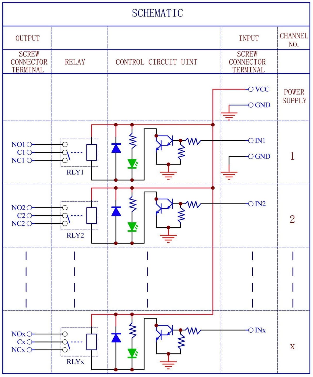
Yes it is.
It looks like connecting GND to GND of the spark and the - of the SSR board will work.
The ‘active’ state of the SSR minus terminal is that it is pulled down. This means in your circuit, the relay is not powered. The ‘not-active’ state that the pin is pulled to 5V through a resistor and LED. the LED can cause the pull-up to only reach 3V on the pin, but that is still enough to open the darling transistor on the relay board.
The downside here is that active on the SSR board means not-active on the relay board. On a digital actuator, you can set it to inverted. However, the fallback non-configured state, when no digital actuator is driving it could still mean that the relay coil is powered. That’s a risk and downside of using the SSR boards this way.
ok thanks for blowing up my brain here - take a min to digest.
Simple breakdown - are you telling me that the exp. board and power can potentially always be on? Cause the Relay boards can be wired to be (NO) normally open or (NC) normally closed if that needs to change. I just want to make sure cause the relays will power all my pumps, AC Unit, heater element etc. and I dont want them to be on all the time.
Also should the expectation be that the LED of the relay board should always be ON or only ON when they are engaged?
I doubt ive said this enough - but thank you for all your guys help!
I should probably ask for a pen & paper sketch of what you mean (im visual) for a connection from the exp. board and from the Spark. I just want to make sure Im on the right page. Ill ask my electrician friends but that will take more time for sure.
You don’t have a good option here I think.
The transistor on the relay board has a pulldown. You are connecting the output pin of the SSR board that has a pull-up. If the SSR board has the pull-down not activated, then the pull-up is stronger than the pull-down on the relay board and the transistor opens.
The SSR-board was designed to be minimal in components and just work with SSRs. When used as a digital output that should be driven high for an active state, it just doesn’t fit very well. I can’t make the situation any prettier.