How to connect powerswitch tail to BrewPi Spark

Hello, first post here. I am working on building a fermentation chamber. I almost have everything I need and I just ordered the BrewPi Spark. I’ve been looking around everywhere trying to find a guide on how to wire up powerswitch tail II to the BrewPi Spark. Has anyone used the powerswitch tails with the BrewPi Spark, and if so, could you provide me with some instructions on how to wire these up? What type of cabling is needed between the powerswitch tail and the BrewPi Spark? I have my raspberry pi up and running with BrewPi, but when it comes to electrical wiring, etc, I am completely lost. Any help would be appreciated. I am excited to get my ferm chamber up and running with the BrewPi! :smile:

Thanks!

I just did a quick search on the interwebs (I had never heard or seen these devices) and they just seem to be pretty simple switching devices that work much like a SSR. Just from what I read/saw they seem to switch on/off from a DC signal so wiring them should be pretty straight forward; positive to positive negative to negative. The only thing I would suggest is you make sure they are rated for the amperage you will be pulling on the fridge. You want to make sure the device can handle the load and not burn out.

Cheers,
-Stephen

1 Like

I have one connected - just go into test mode and power something easy on like a light. You may need to reverse the wires as it is sensitive the + and - leads. dont worry about the ground. If it helps, I used solid core ethernet wire to run to the leads from the spark v2.

Awesome. Thanks. I think I got it all wired up and working. I am having an issue with output 1 though that’s plugged into my second powerswitch tail for the heater. In test mode, I try to manually switch it on, and it flips on for a split second then turns off. I can’t seem to get it to constant stay on. The output 0 though works perfectly fine. In test mode I turn it on and it stays on. Now if I take the powerswitch tail plugged into output 1 and put it into output 2 and switch it on, it stays on no problem. Does anyone know why this would happen? I checked all the connections and the wiring seems perfect. Also, when I set it in Beer Constant mode, and set the temp really high to something like 100F, the heater won’t kick on. Last night I actually somehow got the heater to work fine in test mode and beer constant mode, but I had unplugged everything and plugged it back in today and now it won’t work again. Unable to keep the heater hooked up to output 1 to stay on… Perhaps it’s a setting I need to adjust?

Sounds to me like a wiring issue somewhere on that tail, or g*d forbid: a bad tail. Can you power the heater from the good tail that works consistently for the cooling function? What kind of wire is that switching the relay/taiil?

I don’t think it’s an issue with the powerswitch tail. Because I’ll unplug it from the digital output 1, plug it into any of the other digital outputs (0,2,3) and it powers on no problem. I’ll also take the tail that consistently turns on (plugged into digital output 0), plug it into digital output 1 and it won’t stay on. I think that maybe it’s an issue with the digital output 1 on the spark… The wiring I’m using is some speaker cabling I had laying around. Probably a low gauge of some sort. And yes, I can power the heater from the “good” tail that’s plugged into digital output 0. Nothing seems to work on digital output 1… Quick video below showing how on digital output 0, it will stay consistently on. But digital output 1 won’t stay on.

Here’s another clip showing only having one tail plugged in to output 1, and it won’t stay on. Then, plugging that same tail into output 0 and it will stay on.

For now, I have been able to setup the Spark to run with digital outputs 2 and 3 and everything works fine. Still concerning though that I can’t get digital output 1 to work… Perhaps a defective spark?

Do you have actuators installed in device manager? Perhaps it is a PWM update that is turning the output off again.

I am not saying that this is not something that should be disabled when in test mode, but I’d like to find out why it happens.
It would also be helpful if you post the output of the control algorithm tab.

Hi @Elco, it did show that PWM actuators were detected on outputs 0 and 1. Currently I have it setup to use outputs 2 and 3 and everything works fine.
I’d be glad to help investigate the issue. Should I try and set it up again to use outputs 0 and 1 and then send the output in the Control Algorithm page?

Actually, now I just tried testing the heater which is connected to digital output 3, and it is behaving just like the videos I posted above. It will no longer stay constant on. Yesterday after a reset to default, then setting up the 2 powerswitch tails on outputs 2 and 3, everything was fine. Nothing changed between then and this morning. Now the same behavior is happening on output 3, that was reported above on output 1. Below is the algorithm page output:

{
“kind”: “Control”,
“pids”: [
{
“kind”: “Pid”,
“name”: “heater1”,
“enabled”: true,
“setPoint”: {
“kind”: “SetPointSimple”,
“value”: null
},
“inputSensor”: {
“kind”: “TempSensor”,
“name”: “fridge”,
“sensor”: {
“kind”: “OneWireTempSensor”,
“value”: 20.1875,
“connected”: false,
“address”: “287A6435070000F4”,
“calibrationOffset”: 0
}
},
“inputError”: 0,
“Kp”: 5.5547,
“Ti”: 600,
“Td”: 60,
“p”: 0,
“i”: 0,
“d”: 0,
“actuatorIsNegative”: false,
“outputActuator”: {
“kind”: “ActuatorPwm”,
“value”: 0,
“period”: 4,
“minVal”: 0,
“maxVal”: 100,
“target”: {
“kind”: “ActuatorMutexDriver”,
“mutexGroup”: {
“kind”: “ActuatorMutexGroup”,
“deadTime”: 1800000,
“lastActiveTime”: 4293167296
},
“target”: {
“kind”: “ActuatorPin”,
“state”: false,
“pin”: 16,
“invert”: false
}
}
}
},
{
“kind”: “Pid”,
“name”: “heater2”,
“enabled”: true,
“setPoint”: {
“kind”: “SetPointSimple”,
“value”: null
},
“inputSensor”: {
“kind”: “TempSensor”,
“name”: “beer2”,
“sensor”: {
“kind”: “TempSensorDisconnected”,
“value”: null,
“connected”: false
}
},
“inputError”: 0,
“Kp”: 5.5547,
“Ti”: 600,
“Td”: 60,
“p”: 0,
“i”: 0,
“d”: 0,
“actuatorIsNegative”: false,
“outputActuator”: {
“kind”: “ActuatorPwm”,
“value”: 0,
“period”: 4,
“minVal”: 0,
“maxVal”: 100,
“target”: {
“kind”: “ActuatorMutexDriver”,
“mutexGroup”: {
“kind”: “ActuatorMutexGroup”,
“deadTime”: 1800000,
“lastActiveTime”: 4293167296
},
“target”: {
“kind”: “ActuatorNop”,
“state”: false
}
}
}
},
{
“kind”: “Pid”,
“name”: “cooler”,
“enabled”: true,
“setPoint”: {
“kind”: “SetPointSimple”,
“value”: null
},
“inputSensor”: {
“kind”: “TempSensor”,
“name”: “fridge”,
“sensor”: {
“kind”: “OneWireTempSensor”,
“value”: 20.1875,
“connected”: false,
“address”: “287A6435070000F4”,
“calibrationOffset”: 0
}
},
“inputError”: 0,
“Kp”: 5.5547,
“Ti”: 1800,
“Td”: 200,
“p”: 0,
“i”: 0,
“d”: 0,
“actuatorIsNegative”: true,
“outputActuator”: {
“kind”: “ActuatorPwm”,
“value”: 0,
“period”: 1200,
“minVal”: 0,
“maxVal”: 100,
“target”: {
“kind”: “ActuatorMutexDriver”,
“mutexGroup”: {
“kind”: “ActuatorMutexGroup”,
“deadTime”: 1800000,
“lastActiveTime”: 4293167296
},
“target”: {
“kind”: “ActuatorTimeLimited”,
“minOnTime”: 120,
“minOffTime”: 180,
“maxOnTime”: 65535,
“active”: false,
“target”: {
“kind”: “ActuatorPin”,
“state”: false,
“pin”: 17,
“invert”: false
}
}
}
}
},
{
“kind”: “Pid”,
“name”: “beer2fridge”,
“enabled”: true,
“setPoint”: {
“kind”: “SetPointSimple”,
“value”: null
},
“inputSensor”: {
“kind”: “TempSensor”,
“name”: “beer1”,
“sensor”: {
“kind”: “OneWireTempSensor”,
“value”: 21.4375,
“connected”: false,
“address”: “281B8F3607000022”,
“calibrationOffset”: 0
}
},
“inputError”: 0,
“Kp”: 1.1094,
“Ti”: 7200,
“Td”: 1200,
“p”: 0,
“i”: 0,
“d”: 0,
“actuatorIsNegative”: false,
“outputActuator”: {
“kind”: “ActuatorSetPoint”,
“targetSetPoint”: {
“kind”: “SetPointSimple”,
“value”: null
},
“targetSensor”: {
“kind”: “TempSensor”,
“name”: “fridge”,
“sensor”: {
“kind”: “OneWireTempSensor”,
“value”: 20.1875,
“connected”: false,
“address”: “287A6435070000F4”,
“calibrationOffset”: 0
}
},
“referenceSetPoint”: {
“kind”: “SetPointSimple”,
“value”: null
},
“output”: 0,
“achieved”: 127.9961,
“minimum”: -10,
“maximum”: 10
}
}
],
“sensors”: [
{
“kind”: “TempSensor”,
“name”: “fridge”,
“sensor”: {
“kind”: “OneWireTempSensor”,
“value”: 20.1875,
“connected”: false,
“address”: “287A6435070000F4”,
“calibrationOffset”: 0
}
},
{
“kind”: “TempSensor”,
“name”: “beer1”,
“sensor”: {
“kind”: “OneWireTempSensor”,
“value”: 21.4375,
“connected”: false,
“address”: “281B8F3607000022”,
“calibrationOffset”: 0
}
},
{
“kind”: “TempSensor”,
“name”: “beer2”,
“sensor”: {
“kind”: “TempSensorDisconnected”,
“value”: null,
“connected”: false
}
}
],
“actuators”: [
{
“kind”: “ActuatorPwm”,
“value”: 0,
“period”: 1200,
“minVal”: 0,
“maxVal”: 100,
“target”: {
“kind”: “ActuatorMutexDriver”,
“mutexGroup”: {
“kind”: “ActuatorMutexGroup”,
“deadTime”: 1800000,
“lastActiveTime”: 4293167296
},
“target”: {
“kind”: “ActuatorTimeLimited”,
“minOnTime”: 120,
“minOffTime”: 180,
“maxOnTime”: 65535,
“active”: false,
“target”: {
“kind”: “ActuatorPin”,
“state”: false,
“pin”: 17,
“invert”: false
}
}
}
},
{
“kind”: “ActuatorPwm”,
“value”: 0,
“period”: 4,
“minVal”: 0,
“maxVal”: 100,
“target”: {
“kind”: “ActuatorMutexDriver”,
“mutexGroup”: {
“kind”: “ActuatorMutexGroup”,
“deadTime”: 1800000,
“lastActiveTime”: 4293167296
},
“target”: {
“kind”: “ActuatorPin”,
“state”: false,
“pin”: 16,
“invert”: false
}
}
},
{
“kind”: “ActuatorPwm”,
“value”: 0,
“period”: 4,
“minVal”: 0,
“maxVal”: 100,
“target”: {
“kind”: “ActuatorMutexDriver”,
“mutexGroup”: {
“kind”: “ActuatorMutexGroup”,
“deadTime”: 1800000,
“lastActiveTime”: 4293167296
},
“target”: {
“kind”: “ActuatorNop”,
“state”: false
}
}
}
],
“setpoints”: [
{
“kind”: “SetPointNamed”,
“name”: “beer1set”,
“setPoint”: {
“kind”: “SetPointSimple”,
“value”: null
}
},
{
“kind”: “SetPointNamed”,
“name”: “beer2set”,
“setPoint”: {
“kind”: “SetPointSimple”,
“value”: null
}
},
{
“kind”: “SetPointNamed”,
“name”: “fridgeset”,
“setPoint”: {
“kind”: “SetPointSimple”,
“value”: null
}
}
]
}

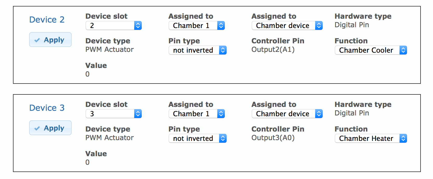
Here’s also a screenshot of the 2 actuators in the device list:

If the pins are installed as PWM actuator, they will be set by the PWM module.
If you are toggling them with the button in test mode, the PWM module will still turn them on and off.

I could add a bit of code to prevent that from happening in test mode. I do not think there is any problem though, as you have confirmed that your outputs work and as soon as you switch to a fridge or beer control mode, you’ll want the PWM modules to control them instead of the button.

Right, when I test in beer / fridge constant mode, the switches turn on and stay on as expected. Wasn’t sure if there was any concern that in test mode it would not stay on.

First off I’ll say that the following is totally my fault, and I have since completed a long-planned move to solid state relays, like those sold on the BrewPi store. With that mea culpa out of the way:

I had 2 PowerSwitch tails controlling my fridge and heater and they worked flawlessly for several months. Upon upgrading to BrewPi 0.4.x, both in software and in firmware, I started to see the toggling behavior described in the OP, on my heating element. I had chalked it up to the PowerSwitch getting internally damaged during a move which coincided with the upgrade, and without testing outside of the BrewPi context I just assumed it was broken. So I did a tear-down out of curiosity, chopped it up to keep various parts for later, and threw the rest away!

But now I suspect there was nothing wrong with the mechanical relay; it was just being power-cycled quickly by the BrewPi unit during Test mode. D’oh! So take heed if you have a PowerSwitch or other mechanical relay that’s clicking a lot: if it acts weird, especially in Test mode, don’t assume that it’s broken. Try it under normal BrewPi operating conditions or perhaps just test it with a standard 9V battery to mimic a steady control signal!

1 Like

Yikes! I’m glad the issue didn’t turn out to be an issue with the powerswitch tail. Sounds like that piece of code @Elco mentions above might be a worthwhile enhancement…

You guessed wrong, but did chop up that powerswitch tail for no reason.
Since version 0.4, the actuators are driven with PWM. For the heater, the period is 4 seconds. So that is On and Off every 4 seconds (default period). Mechanical relays are not good at switching so often, SSRs are much better.

So yes, the frequent switching is normal and by design. It is used to modulate the heater to a lower power instead of crude ON/OFF.

My freezer is on output 0 and has no problem.

Put heater on output 1 would exhibit this problem in test mode. So I moved the heater to output 2 and it worked in test mode. So I kept that setup and entered my beer profile. Running the profile, the heater never comes on. Thankfully for now I am in the cold crash cycle going down to 0˚C, so the heater isn’t needed any way.

I am not technical and don’t really understand the comments to PWM, or if this issue was resolved or not and what the critical issue is. But it seems I basically have the same problem except I work in test mode and fail in profile which is the opposite of dominic if I understand correctly.

I am trying to guess the answer here. Is it possible if I move my heater back to output 1 that it would not work in test mode, but would start to function for beer profile?

Everything works as expected when in constant modes. But for some reason, the heater (output 1) does not stay on in test mode. This isn’t as big of an issue since the heater turns on and stays on as expected in constant mode.

But it’s a bigger deal for me because I have the opposite problem. The heater stays on in Test mode but not in the operational modes.

Can you show your device setup in device manager?