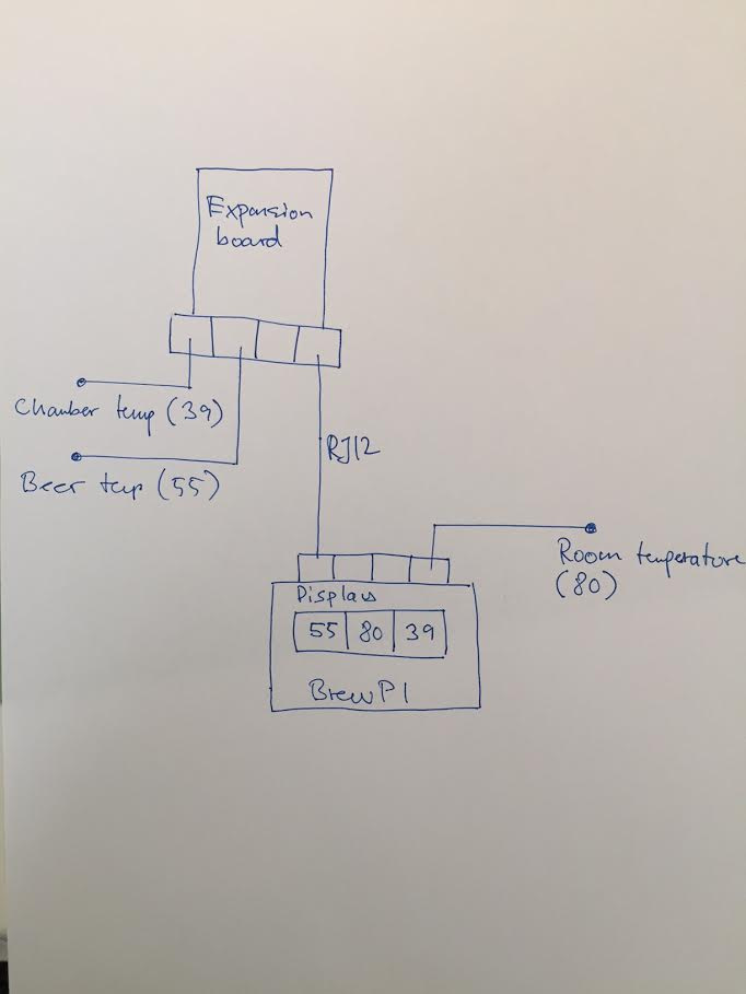
I got configuration issues with BrewPi onewire temperature sensors from BrewPi web interface. Three temperature sensors are currently connected in accordance with the diagram below. On the diagram is shown the last two digits in the “onewire” address.
All three sensors shows up on the BrewPi display and indicate temperature. The temperature sensor order is shown on the drawing as the last two digits in the sensor address.
Questions
How to control the sensor order on the display, when two sensors are connected to BrewPi via the expansion board?
The last two digits from “onewire” address are shown on the drawing of BrewPi above.
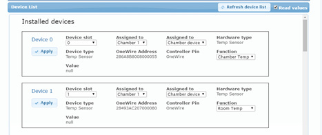
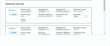
What is the difference between “Installed” and “Detected” devices?
Why is only one sensor detected, when three sensors are shown on the BrewPi display?
BrewPi has status “Script running” in Test mode
4. Why does “Value” indicate null and not a temperature (ref. below) (I imagine it is because that the sensors are not detected)
Are all 3 sensors shown and reading values on the display in test mode?
Try uninstalling all sensors (set the function to None and apply).
The ‘Installed sensors’ are sensors that are added. They might not be connected, the address is just remembered.
The detected sensors are sensors that are found, but not installed.
Hi Elco
Thanks for your advice!
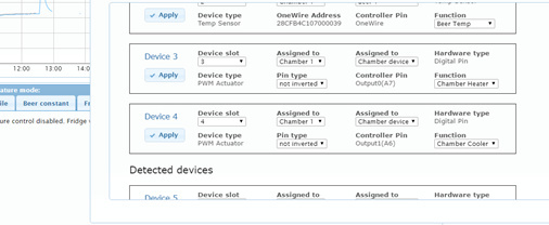
Now everything seem to be working. All 5 devices are installed, 3 temperature and controls of the two SSR’s for heating and cooling.
It obviously not possibly to install temperature devices that are connected to the BrewPI Spark through the expansion board, which what I tried.
During installation temperature devices must be connected directly to the input on BrewPI Spark?
When sensors are installed, they may be connected to the expansion board without need of further configuration?
Are the SSR’s addressed in the order they are connected to the expansion board?
It should definitely be possible to install sensors connected via the expansion boards. If you cannot find the sensors when plugged in there, you have a problem with your cable.
The SSR expansion board should show up as 2 devices on OneWire, output A and output B.
Hi Elco,
The heating and cooling control of the SSR’s are configured as shown below, but the SSR’s are not activated when starting to heat in “Beer constant” mode (30°C set-point), since there is almost no voltage drop across the SSR input terminal, when the heater suppose to be activated.
Hi Elco,
Are all the 6 wires in the RJ12 cable used in communication between BrewPI and the expansion board?
I have been using an RJ11 cable with 4 wires and housing size same as RJ12.
Hi Elco and Dan
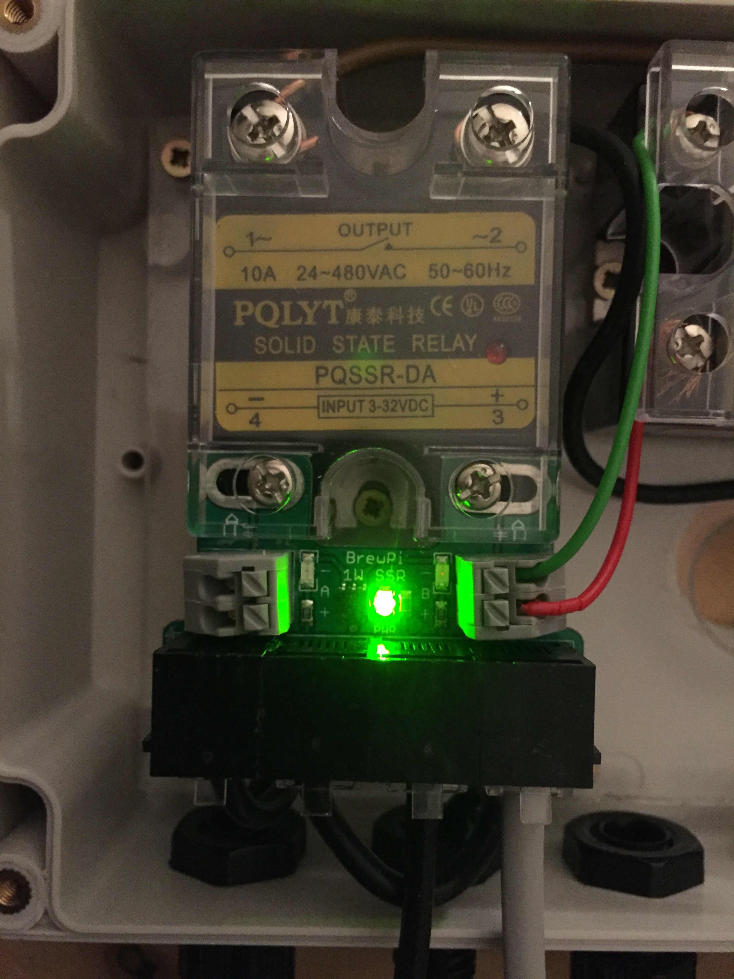
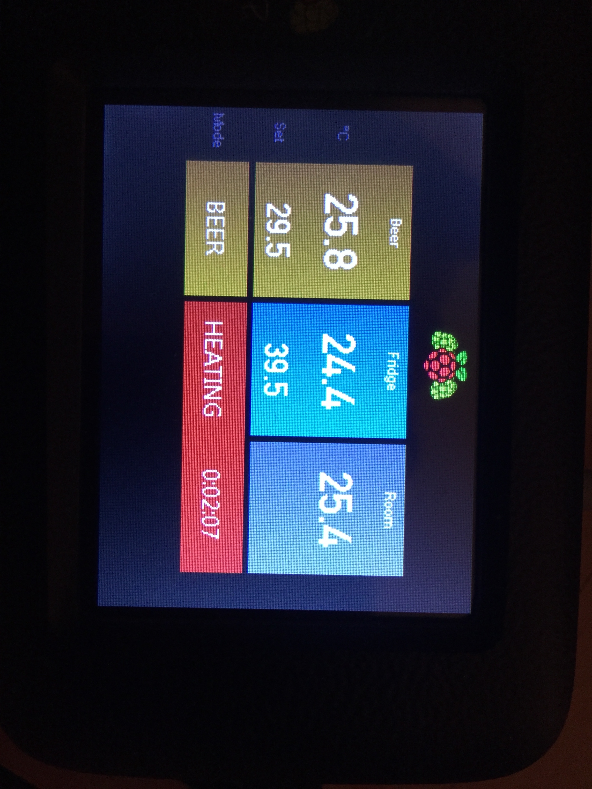
I still got a strange issue on controlling SSR through the expansion board. On the picture below, BrewPI Spark is connected to the expansion board with the 4-wire RJ11 (green diode on the expansion board indicates connection works). The SSR is however not activated even it should (red diode on the SSR does not turn red), when running the script “Beer constant” mode (29,5°C set-point).
Please advise
The SSR requires 3-30 V for activation. The voltage across the SSR input terminals are only app. 0.5 V DC, even when running in “Beer constant mode”.
The green LED indicates that the board gets 5V, not that the OneWire connection is successful. The data pin could still be not connected.
If you plug a temp sensor in the breakout board and it doesn’t show up, I think there is something wrong with your cable.
Take a good look at your RJ11 connectors. It is possible that you slightly damaged the plastic, preventing one pin to connect. You can also post a photo of the top and bottom of the expansion board here if you want me to have a look. Higher resolution than this one please.
Hi Elco,
Here are the photo’s you requested. All temperature sensors are now connected to the expansion board and indicating actual temperature on BrewPi Spark display, which means that all cables are ok. The control voltage accross the SSR terminals marked A- and +A is about 0.5 V DC even display on BrewPi says heating?
Is it nessesary that the power side (secondary side) of the SSR must have 220V connected, in order to have the SSR working properly?
BR Ken
Hi Elco,
Everything seems to be working now . The two outputs A and B were not properly installed even they were visible as installed devices. I uninstalled both outputs by applying function “None”, and installed them both again, after they were detected.


 . The two outputs A and B were not properly installed even they were visible as installed devices. I uninstalled both outputs by applying function “None”, and installed them both again, after they were detected.