I have all almost all my pieces together (save for a heater) but am having a bit of trouble wrapping my head around the wiring.
Parts List:
Fridge - Frigidair 4.4cu inch refrigerator. 0.806Amp / 115V / PTC starter relay
Heater - TBD but looking at a 110v / 60W tube heater like this: http://www.e-tradecounter.co.uk/p-2855-110v-tubular-heater.aspx
2x 10A SSR
Brewpi Spark
Raspberry Pi B+ and 5V 2A Switching Power Supply
3x one wire temperature probes
I have a few questions:
-
In the fridge hacking guide terminals 3 and 4 of the two SSRs are
labelled as Ground and Control Respectively. So I am guessing this
means that these two wires are connected to the Brewpi Spark via the
Digital Outputs? If this is the case how exactly are these
Grounded? Since the Spark board is powered via USB from the
Raspberry B+ and that in turn only has a Live and Neutral power
supply, how could this be Grounded? -
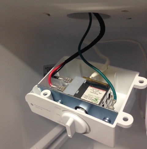
The temp probes also have a Ground wire and doesn’t the same apply
to them as well? Alternatively should I connect the ground wires on
the temp probes in the fridge to the green wire from the fridge
thermostat which is grounded on the metal frame of the fridge? (see
image below of interior fridge thermostat wiring) -
In Image D below you will see the Neutral White wire coming out of
the PTC relay, which goes into the back of the connector box in
Image C (not visible in the photo) into the fridge, back out of the
fridge (still white) to the connector which meets the white Neutral
wire of the Wall plug wire at the bottom of Image C. I’ve indicated
this “detour” at the bottom of my proposed wiring diagram with a
circle around a “?” as I don’t know where this white wire is going
and for what purpose. Is it reasonable to connect this white wire
after the “detour” to the the neutral wire coming out of the heating
element just before returning to the wall plug? Anyone have any
ideas what it might be?
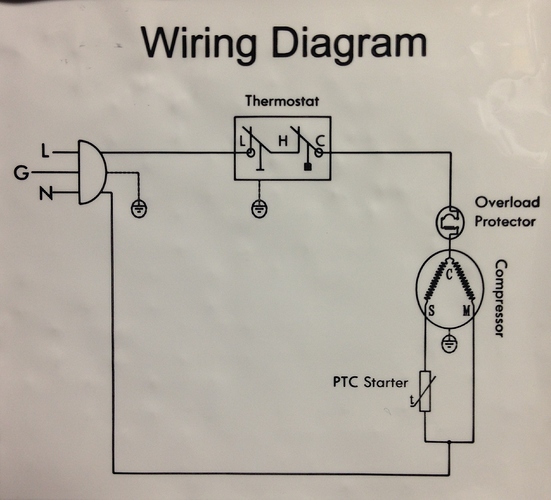
Image A - Here is existing wiring diagram for my fridge:
Image B - Below you can see the wall Black plug wire (Live Black and Neutral white and Ground green) coming up from the bottom of the image to the connector that leads to the interior fridge thermostat (Live Black, Neutral Red). Here the Red wire (sheathed in white) coming from the thermostat changes to Blue after and leads to the Compressor.
Image C - Here you can see the blue wire from the thermostat going to what I think is the overload protector and then to the compressor, which then comes out of the PTC relay White.
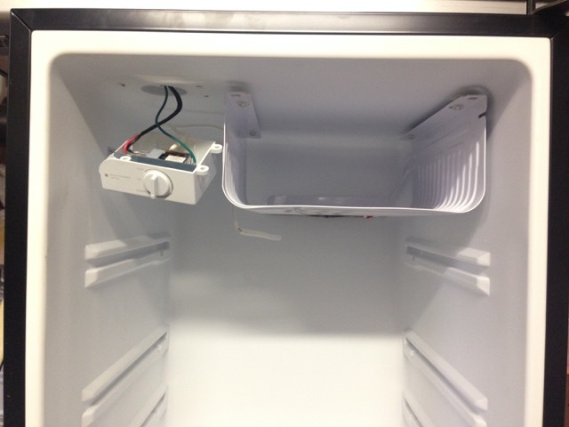
Image D - Inside the fridge is the thermostat and probe. It appears that the Black wire is Live from the Wall plug, the Red wire goes to the overload protector then the compressor and the Green is grounded on the metal frame at the back of the fridge. I plan to remove the thermostat and use these existing 3 wires to hook up 2 interior fridge temperature probes to one of the Brewpi Spark’s one wire RJ12 ports:

Here is my proposed wiring diagram. I realized the only thing I know I have left out of this diagram is the 5V 2amp power supply for the Raspberry Pi, after the main power cable splits to go to the Pi and the SSRs. I have opened up this “wall hog” and am planning to hard wire it between this split and the raspberry pi.
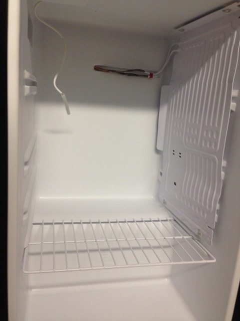
I’ve already modified the interior of the fridge to fit my fermentor from what it was:

To this:

