Hey Guys, I’m new to these forums, but I just picked up my BrewPi setup recently complete with all sensors and SSRs to build out my new fermentation chamber. I managed to pick up a frigidaire glass-door beverage center (FFBC46F5LS) for a really good deal off of craig’s list, but now that I’m looking at the wiring, I’m beginning to get a little intimidated. I’m a software engineer by profession and I never really got too much into electrical (other than building my own computers), so when I realized that the fridge I got has a digital readout / temperature control board instead of the usual rotary switch style thermostat - I began to feel like I might have bit off more than I can chew.
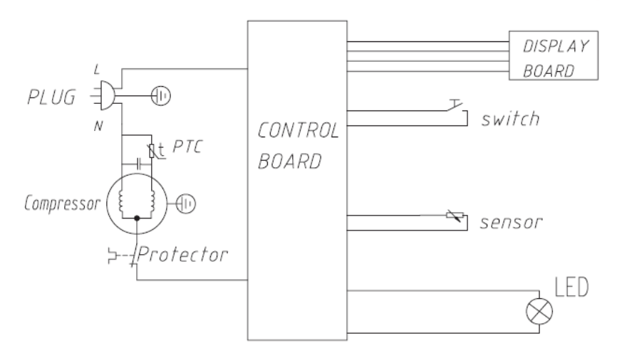
Attached is a picture of the basic wiring diagram:
The fundamental challenge I’m mulling over is how the control board pictured changes the steps shown in the fridge hacking guide. I know others have hacked fridges like this, but from what I can find, they jumpered the compressor control switch on the control board and then they made a switchable cord - I’m thinking I could do the same, but it’d be a shame to lose the light and temperature readout since those would only show when the compressor was running. Also, while I’m not an electrical expert, I feel like switching from completely off to on and running has got to be a bigger current spike - I’m wondering if that would have any impact on the system longevity-wise.
I’m open to suggestions, and ideally, if someone has already tackled a fridge like this and can shed any light on how best to tackle this hack.
Based on this very simple schematic, I think live goes in on top of the control board and goes back to the compressor on the bottom. So the control board is breaking the live wire, based on the sensor input.
I think you could put your SSR basically in place of the control board on the compressor side, but leave it for measurement.
The schematic is not entirely complete, because there does not seem to be a neutral wire to the control board. I think they left out the power to the control board and are just showing that it switches the live wire.
If you buy a switch rated for high current, you could even add a switch to let the live wire go through the original control board or through the BrewPi controlled SSR.
Thanks Elco for your help input on this. I bought all the materials for this setup, but had to shelf the fridge hacking project for a couple months due to health / family issues, but now I need to wrap it in a hurry since I need to have my fermenter setup and running shortly.
The idea I was thinking of pursuing was to jumper the live current through the board so that the current was always flowing to two the compressor while plugged in, then, on the compressor side, I would place my SSR to actuate the compressor. This seems in line with what you were suggesting, but your last sentence concerns me.
I had bought a 10amp SSR since, I figured there was no way (even at startup) that this fridge would be pulling more than 10amps, but your last sentence seems to imply I should have bought a higher rated SSR for the setup I’m looking for, is that correct?
Also, another thought, since I have to get this functional quickly - I may do the full integration fridge hack later. I will do it someday so my questions above are still valid, but…
If I were to go about building a switched cord scenario in the interim, would I really need a 40amp SSR as shown on the fridge hacking guide? On the store it says that that SSR is more for high current - heating element type - applications. Also, the outlet this fridge is on is on a 20 amp circuit, so I don’t see why that would even be necessary.
10A is usually sufficient for a fridge. You don’t have to worry about it.
Switching the power cord of the fridge (don’t cut the cord of the fridge, but hack an extension cord instead) is an easy start. Downside is that you don’t have direct control over the compressor and you are also switching your internal light, etc.
So, regarding the setup… The computer, LCD, and LED add a layer of complexity to a fridge, but overall a fridge is a fridge (is a fridge)… They all have some control mechanism that tells the compressor when to run and when to shut off.
Since I was pressed for time, I simply bought a switchable cord - the PowerSwitch Tail II - it’s rated for more than enough current and while it’s mechanical instead of SSR, it will do the job just fine. With the PowerSwitch Tail II, I’m simply switching power to the fridge via that cord with the fridge fully intact.
Next steps (in a couple weeks) I will be doing what is pictured here:
If you scroll through the thread you will notice that he is modifying a Haier fridge - though the control setup seems almost identical to mine - I would bet money it’s basically same control unit for just about every “wine-cooler type fridge.” All he did was jumper the hot lead to the compressor so that when power is supplied to the unit, the compressor runs. Having this jumper, plus a switchable cord seems like the least invasive solution and provides full control over the compressor.
As far as figuring out which connections to jumper, that will likely vary fridge to fridge and will require a wiring diagram and a multimeter - to be certain your doing it correctly, but the link (with pictures) above is likely to be pretty close to what you have.