I want to use my fridge fan any time that heating element is on, the fridge is cooling, or potentially on a PWM of its own to maintain a level of circulation regardless of the heat/cool mode.
So really, I want to OR the outputs for three PWM blocks.
I can probably do this with a 7432 electrically, but hoping that software can do it too.
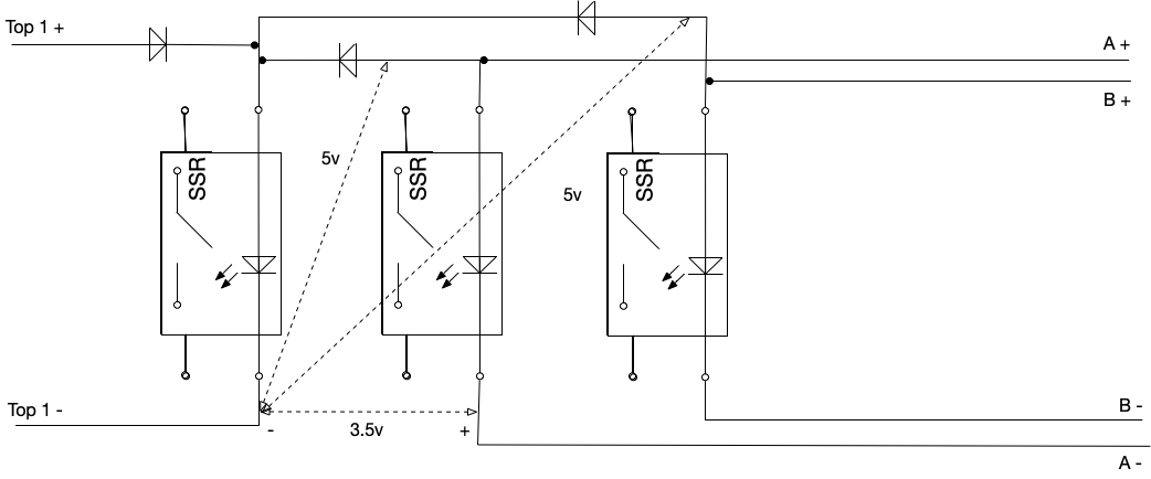
I attempted to OR the three signals with diodes going into the fan SSR, 2 on the SSR expansion, and the other from the spark itself and it seems there is no common ground between the digital pin on the spark and the expansion board.
Is this correct? I get 3.5v across the two GNDs.
I have the spark connected with 12v Power, spark says that the 5v is a 5.04v and the 12v is about 12.05v
Apologies on the diagram quality, I only have omnigraffle, and I dislike it.
So I get 3.5v between the grounds, - on the spark side, and 5v from the spark ground to the + on A/B on the expansion board, neither actuators are active at this point.
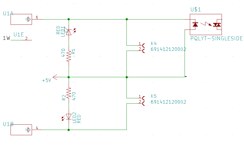
I think I have an idea what the issue is. Because of how the DS2413 works, the negative side is switched.
B+ always has 5V on it and B- is connected to GND on enable.
That makes the diode solution a bit more difficult.
I have been testing this with the latest release and I have been able to produce a setup that works as I need it to, which is really great, so first of all, thanks.
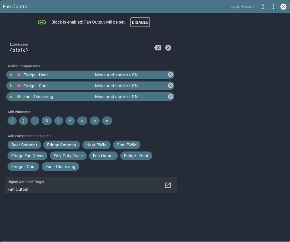
What I have is the standard PWM driving actuators for heat and cool, which I can use the measured state and create and OR situation where either the heat or cool turn on the fan.
But we discussed previously that introducing a PWM to to drive the fan, even when the heat/cool is not activated could be desirable.
So this idea would be, the fan gets turned on by either heat, cool, or the PWM cycle of the fan.
For the PWN to register a duty cycle, it seems that it needs to drive an actuator, which i expected to use as an input into the logical actuator, and that actuator needs to drive a pin. Without the pin the PWN doesn’t drive the actuator.
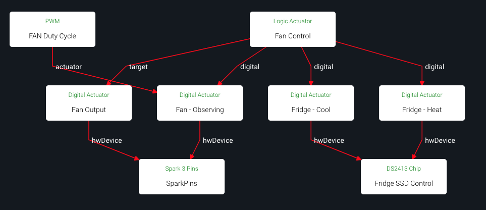
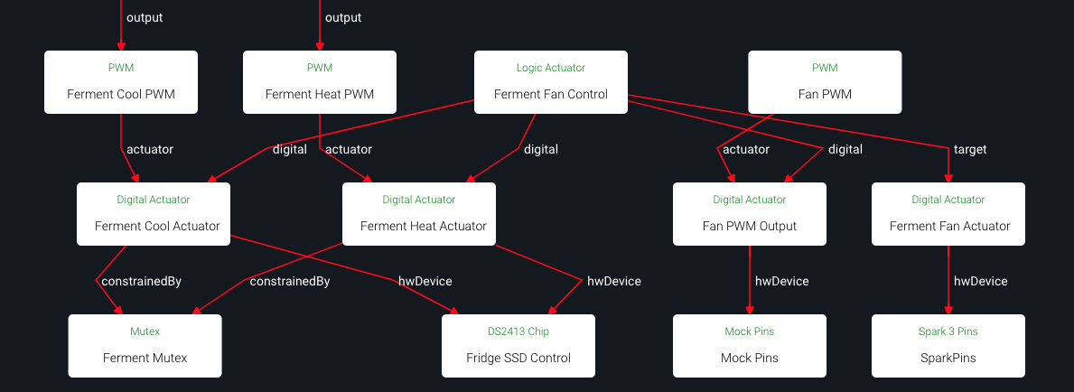
These are the blox I needed to create to make it work where it works exactly as I would like it to.
Also, UI wise, it feels like the Logical Actuator should be below the inputs with arrows towards the Logical Actuator, and above the driven output, which it is now.
The relations diagram is generated automatically, and the Logic Actuator technically “targets” its comparisons. I’ll make an issue to make an exception for it.
Your approach is correct, but may benefit from the new Mock Pins block. You can point Fan - Observing towards that, instead of it taking up a unused real pin.
The interlocking PWM cycles you’re tracking may also cause somewhat patchy fan behavior. This can probably be solved by adding constraints to the Fan Output. Min ON / Min / OFF / Delay OFF may all be useful.
I have found that while in theory, the Fan - Observing block is logical (no pun intended), in practice it is not needed.
Try replacing the target for Fan Control with Fan Output.
Then edit your c comparison to compare the measured state of Fan Output.
This works for my situation and has less blocks.
Now the question…
Is this arrangement risking an undefined response at some point?
Or was this intended or coded so that it works reliably?
Won’t both the Fan PWM (for the slow on/off cycle) and the Logic Block set the pin in that case?
It maybe works because the PWM block turns the pin ON, but the logic block turns it off soon afterwards.
I think using a mock IO pin in between in a cleaner setup. If you make the fan pin both input and output, it is much harder to reason about.