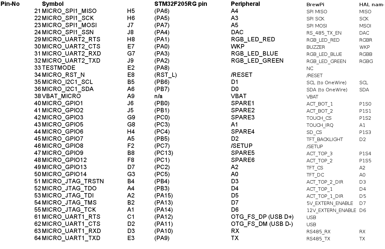
Is the information available which list which pin from the Photon is used for what function? I’d very much like to know which Pins are wired to display, outputs, 1-wire, buzzer and so on.
Or full schematics maybe?
This would be for the Spark v2. Are there differences to the spark v3?
@Elco I am wondering if it would actually be possible to control the complete hardware from Spark by just controlling pins from the particle photon. On the green board from the Spark v2, are there additional controllers onboard light I2C or controllers for the display?
I am trying to add some functionalities to the current firmware. But I need to get some basic understanding first.
Thank you so much! I am just trying to learn a bit so that I may be able to contribute in the future. But after looking into the firmware section on github I am no longer sure if my coding skills are sufficient.
The firmware is indeed pretty complex. PS, the pinout above is for the v3.
Actuals pins are defined in this file:
That would be the definition for the V2.
If you want to toggle some things on/off, I think it would be easier to install some devices as ‘manual actuator’ and control them with a socket message.
Thanks a lot for that. OK, that is going to be a lot of learning, maybe your idea to use a manual actuator is better
Did I understand correctly that the Sparkv2 shield is much more than just a pass-through from the Particle Photon pins? Communication in between shield and Photon is done over I2C and serial?