What is the present status of PID anti-windup?
It’s has been part of the firmware for a long time.
Anti-windup is applied if:
- The actuator (PWM) is clipped to the maximum
- The actuator is not reaching its target value
Why are you asking?
I am trying to understand what happens in detail.
Is this written down somewhere?
Is the integrator reset to zero when we have 100% PWM?
I have overshoots due to integrator windup.
This may seem messy, here is where I could use some help to get on…
Hi again,
I may perhaps be somewhat more specific.
- What happens when anti-windup is applied? Is the integrator reset to zero and inhibited?
- How is “The actuator (PWM) is clipped to the maximum” detected? 100% PWM?
- How is “The actuator is not reaching its target value” detected?
- Am I able to control action or set any parameters for this to take place?
I am looking forward to your reply, I have the feeling that I am on to something good here.
- Anti-windup is a numeric value subtracted from total output.
- Achieved PWM setting != desired PWM setting.
- Achieved PWM value != achieved PWM setting.
- Not really.
For reference, the implementation can be found here.
I do suspect you’re looking in the wrong place. Anti-windup as it is used here is a mechanism intended to handle edge cases. If your I component in the output is causing overshoot, I’d first look at configuration:
- Too little Kp can cause I to rise too much during step response, while being fine-ish in steady state.
- Too much Kp can cause I to be too aggressive.
- Too much Ti can cause I to be too aggressive.
- Too little Td prevents the D portion from counteracting overshoot caused by P and I.
Do you have any PID graph screenshots for steady state / step response?
To add some more detail to Bob’s already good answer:
The reason to have an integrator is to correct for the situation where you end up slightly under the setpoint, in equilibrium, at the point where the heating/cooling from the P part balances out energy losses to the environment. If this situation of being under the setpoint lasts too long, you want to nudge the output up a bit to find a new equilibrium at the setpoint.
The integrator will increase as long as the input of the PID is under the target value. The speed at which this happens is set by Ti, the integrator time constant. For every period Ti, the I-part will increase with an amount equal to the P-part.
You don’t want the integral to increase while you are still approaching the setpoint, so you want a Ti that is pretty long to make the integral increase only slowly.
Anti-windup ensures that the integral doesn’t increase when the output of the PID is already at its maximum, or not at the target value. If the output is not what the PID wants it to be, there is no point in increasing the output target even further.
So anti-windup does not depend on the PID input. If you have a badly configured PID, that sets the output target too high too early, it is not the job of anti-windup to correct that. Anti-windup only prevents integrator increase when the output target cannot be reached.
If you get overshoot from the integral part, it can have 2 reasons:
- Ti is too small. This causes the integrator to increase by much already during the ramp up, instead of during the equilibrium after the ramp up.
- Kp is too low. This causes the ramp up too take much longer than needed, also giving the integral time to increase.
Td (the derivative time constant) should be the last thing you tweak. Start with Td at zero. Get it stable with just PI control. Then you can see if you can increase Kp a bit if you also use a bit of derivative gain to reduce the output when you are moving in the right direction quickly already.
Hi again,
I am implementing a HERMS with a cascade PID. I have it working with 2 P controllers.
Today I decided to turn on I on the MT PID and set the MT PID I = 1000. P is 0.7.
There was no I response. On the PID panel the values on the left with units deg C x h and deg C / h were both zero all the time. I let it reach a stable value.
Where can I go from here?
You can override I, but it’s only temporary. Have you set your Ti setting?
Ti is set to 1000s. What do you mean by override I?
I is the output value from Integral * Kp / Ti. I asked because you actually can manually set the I value. (This is useful if you want to instantly reset the value).
I assume Kp is 0.7?
What is the current temperature error (shown in PID settings)?
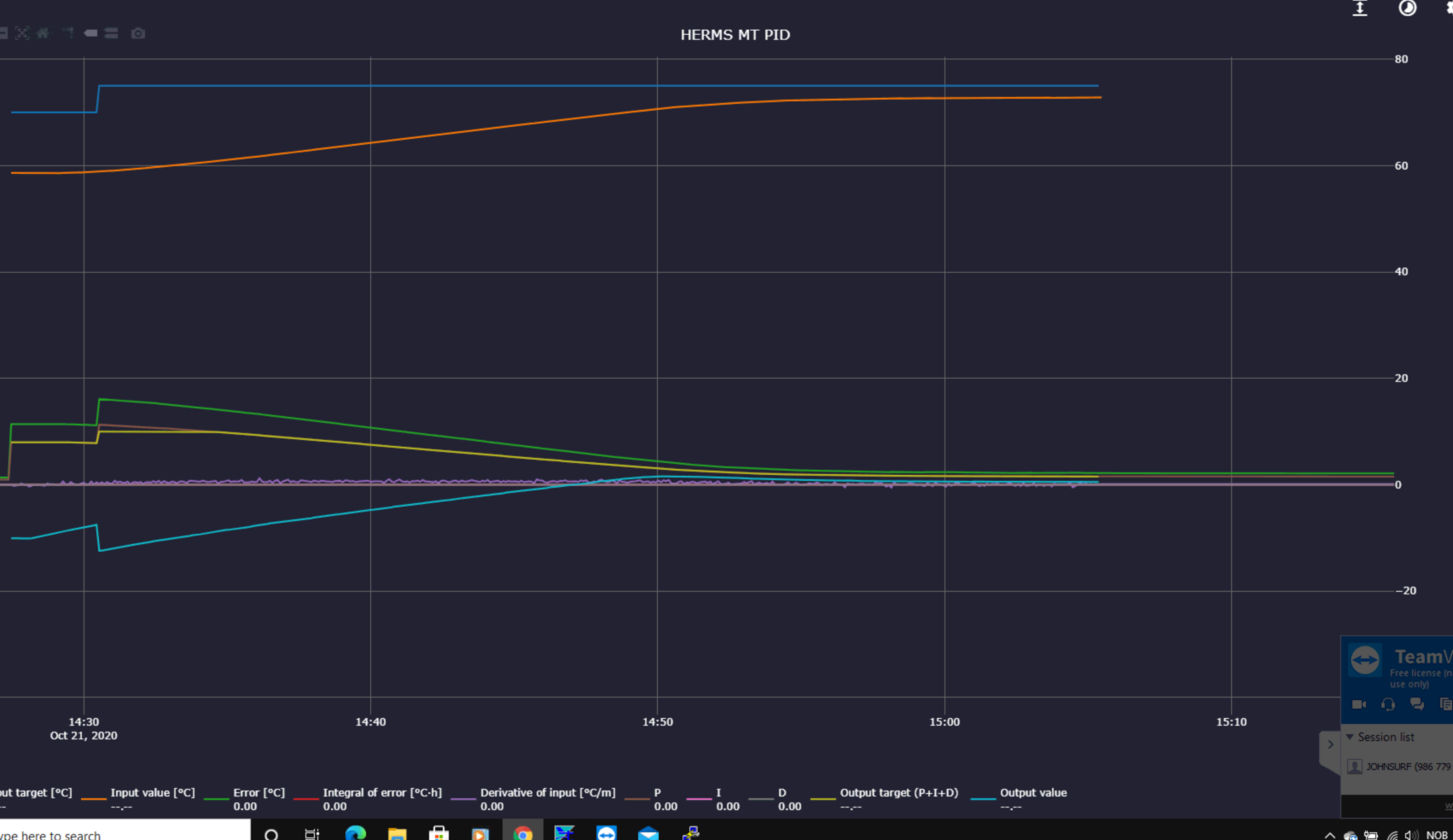
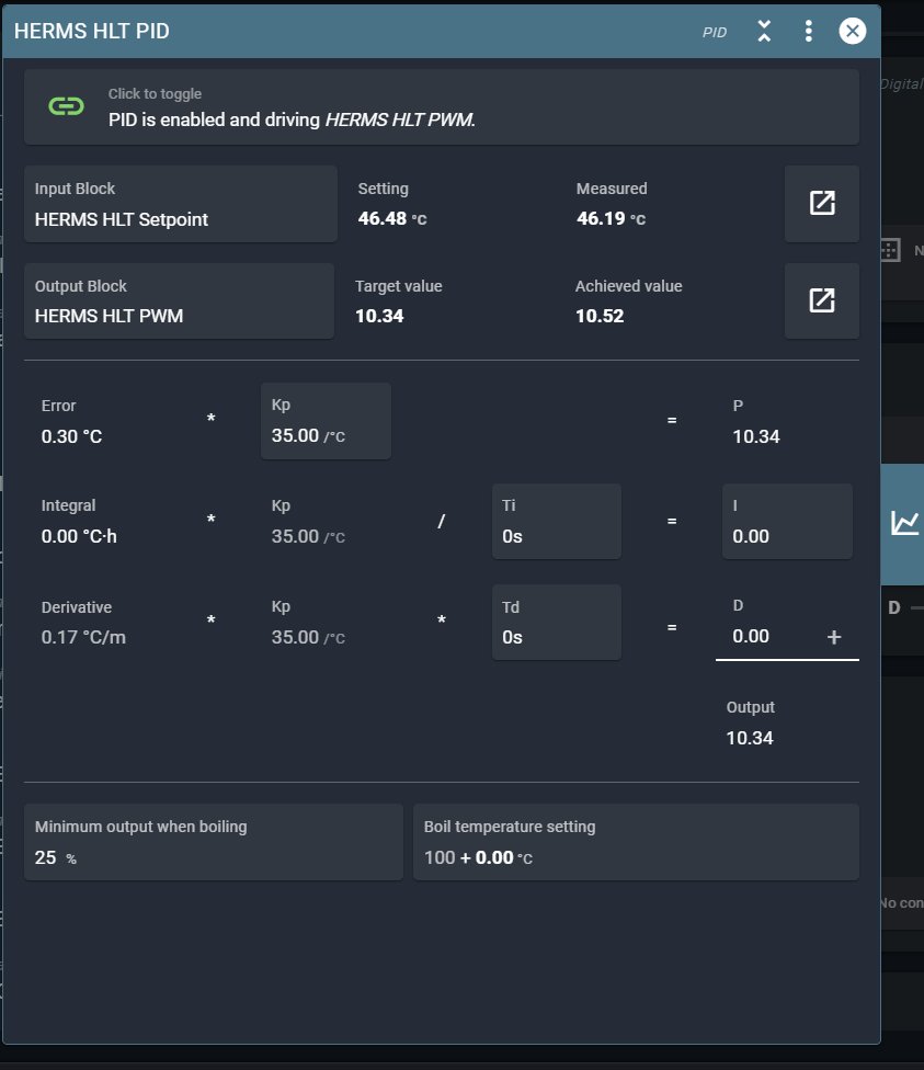
I see that I have not been very precise in my posting.
I attach 2 pix .
The MT PID panel is captured after the run. We have I = Integral * Kp / Ti = I During the run the values of Integral, and consequently I, was zero. This was throughout the whole run
The other pix is the display from the HERMS MT PID.
Is this information helpful?

Your MT PID is disabled. It was on during your run?
Yes it was. I disable when I stop. The MT PID curves are from the run.
The measured value is zero. Is your temp sensor configured correctly in the MT setpoint?
The error is zero, so the P value is zero and the integrator doesn’t increase.
Every second, I will increase by P/Ti.
Hi again and Good Morning,
I feel I am astray in the land of confusion and perhaps overlooking something obvious.
Here is how I experienced my latest runs.
For the HLT PID Kp = 35, Ti = 0 and Td = 0.
For the MT PID Kp = 0.7, Ti = 0 and Td = 0.
I ran this and it worked nicely with no overshoot and found a stable condition.
The temperatures were, as expected, below set values.
The only change I made was MT PID Ti from zero to 1000.
The system still worked nicely as before, but with no signs of integration.
I don’t see how the temperature sensor can go wrong here, perhaps there is something obvious overlooked here?
I also have some questions about anti-windup but I guess it is simplest to keep the issues separate for the time being.
I am attaching a screen-dump of the MT setpoint.
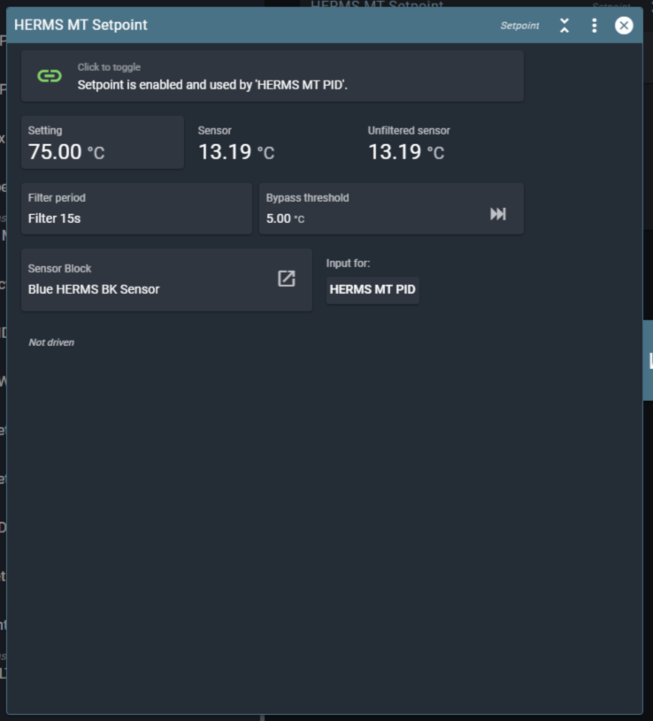
Do you have any suggestions about why the integrator didn’t work?
No. Export your blocks while it doesn’t work. And make a screenshot of the pid and it’s graph.
We don’t have much info to go on now.
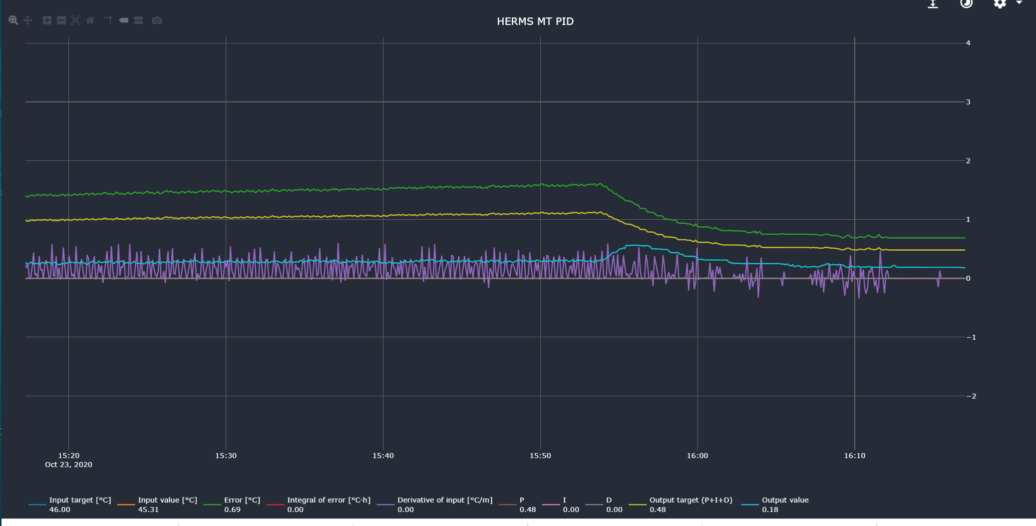
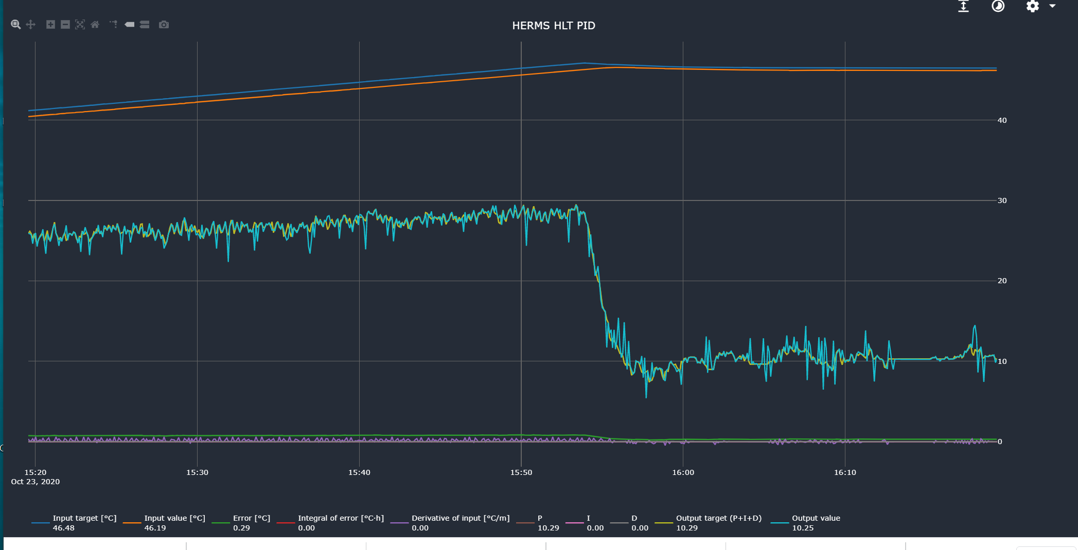
Hi again
Here is, hopefully, the info you requested. The red temp sensor is in the HLT kettle and the blue sensor is in the mash tun kettle.
As you said, these data are taken while the process is running and the integrator is not functioning.
Please let me know if there is more I could send you.
Blue HERMS BK Sensor.json (286 Bytes)
HERMS HLT Actuator.json (282 Bytes) HERMS HLT PID.json (1.3 KB) HERMS HLT PWM.json (455 Bytes) HERMS HLT Setpoint Driver.json (595 Bytes) HERMS HLT Setpoint.json (679 Bytes) HERMS MT PID.json (1.3 KB) HERMS MT Setpoint.json (660 Bytes) Herms Setpoint Profile.json (581 Bytes)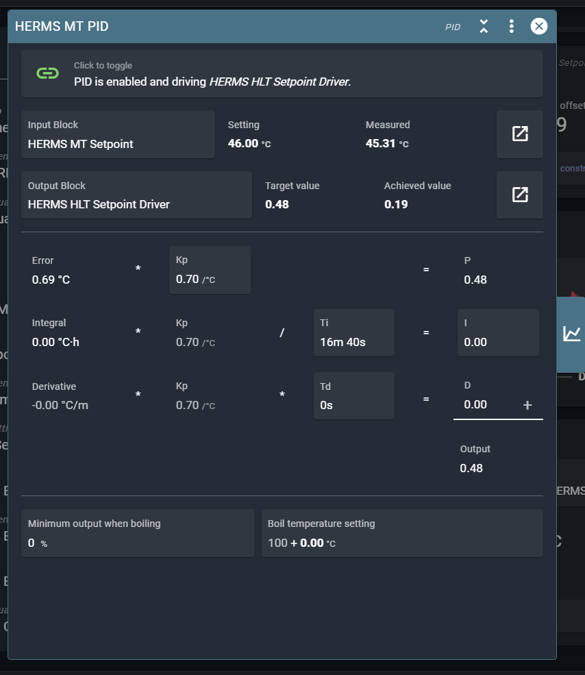

You don’t have to export all the blocks separately. You can choose export blocks from the spark service page on the top-right menu.
This is a bit of a gotcha. I think what we are seeing here is actually anti-windup.
The target for the HLT is not reached (because you have HLT Ti set to zero it gets stuck under the setpoint).
Because the HLT is not reaching its target, anti-windup in the MT PID prevents the HLT target temp from increasing further.
I would try these settings (what I use in my setup):
HLT:
- Kp 40
- Ti 10m
- Td 10s
MT:
- Kp 1
- Ti 5m
- Td 10m
Another recommendation is to have as little water as possible in the HLT. Just enough to submerge the coil.
Thanking you so very much!
Thoughts around anti-windup have been here.
It is an enlightenment for me to see that conditions detected in the HLT PID domain have influence on the MT PID domain. Seems very good!
And yepp!, I will try out your recommendations.
Thanx and cheers.