I is the output value from Integral * Kp / Ti. I asked because you actually can manually set the I value. (This is useful if you want to instantly reset the value).
I assume Kp is 0.7?
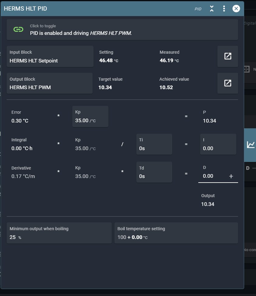
What is the current temperature error (shown in PID settings)?
I is the output value from Integral * Kp / Ti. I asked because you actually can manually set the I value. (This is useful if you want to instantly reset the value).
I assume Kp is 0.7?
What is the current temperature error (shown in PID settings)?
I see that I have not been very precise in my posting.
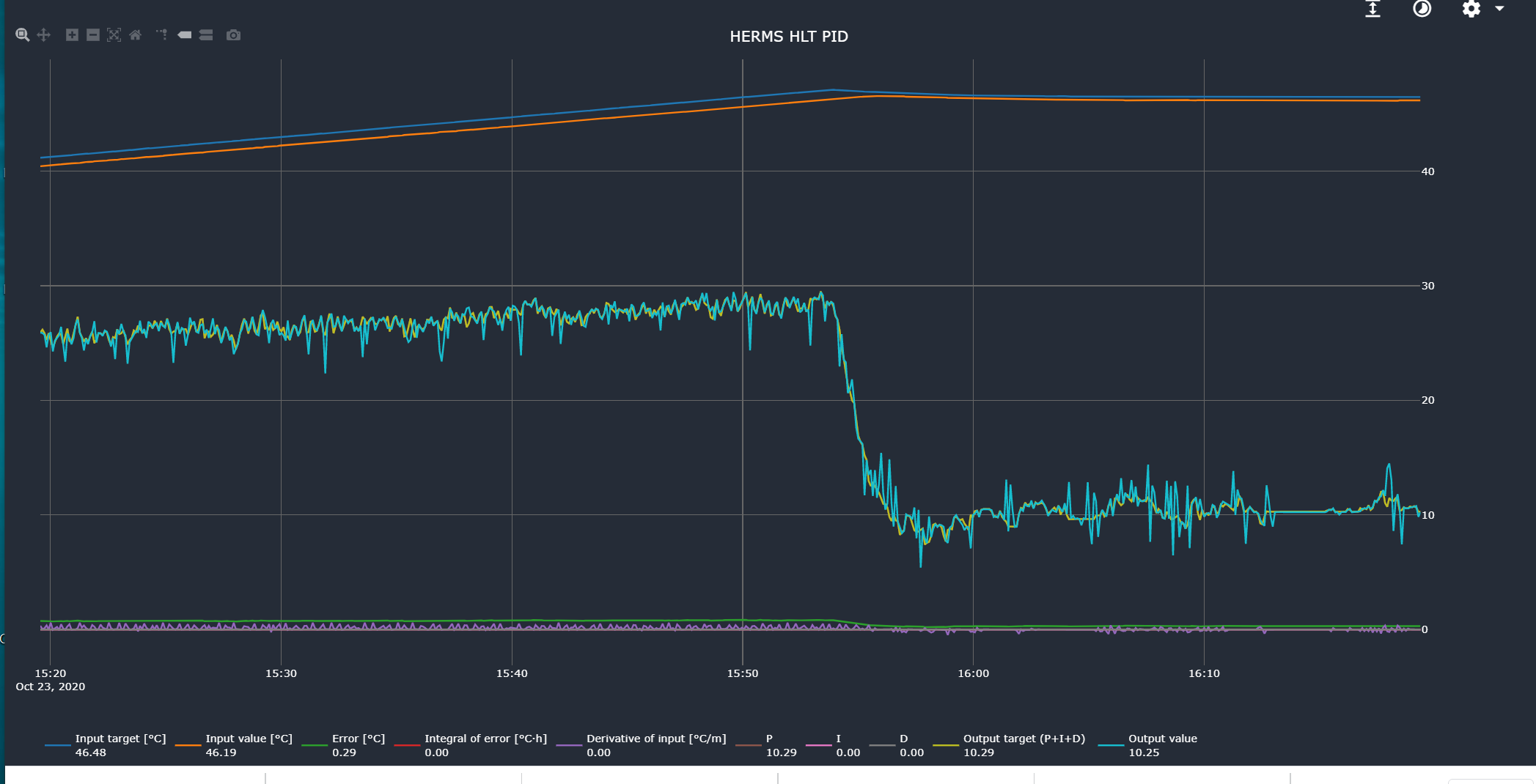
I attach 2 pix .
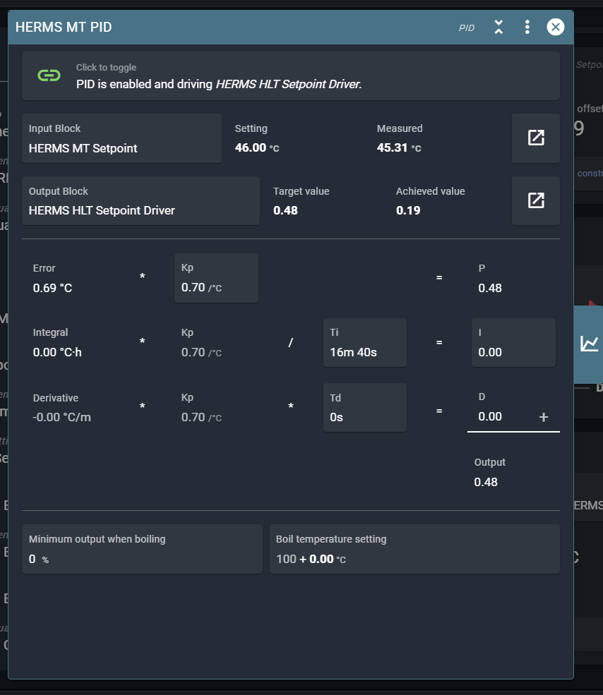
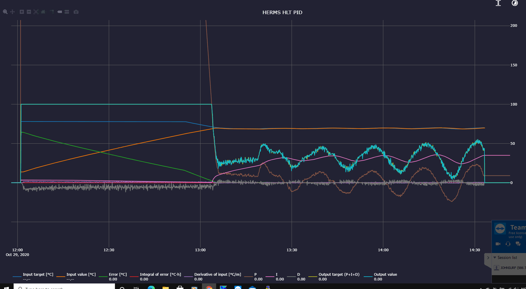
The MT PID panel is captured after the run. We have I = Integral * Kp / Ti = I During the run the values of Integral, and consequently I, was zero. This was throughout the whole run
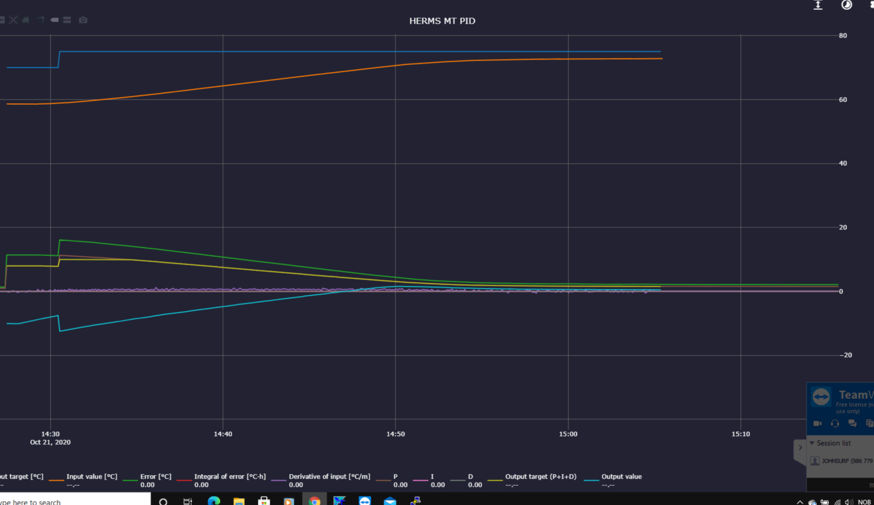
The other pix is the display from the HERMS MT PID.
Is this information helpful?
Your MT PID is disabled. It was on during your run?
Yes it was. I disable when I stop. The MT PID curves are from the run.
The measured value is zero. Is your temp sensor configured correctly in the MT setpoint?
The error is zero, so the P value is zero and the integrator doesn’t increase.
Every second, I will increase by P/Ti.
Hi again and Good Morning,
I feel I am astray in the land of confusion and perhaps overlooking something obvious.
Here is how I experienced my latest runs.
For the HLT PID Kp = 35, Ti = 0 and Td = 0.
For the MT PID Kp = 0.7, Ti = 0 and Td = 0.
I ran this and it worked nicely with no overshoot and found a stable condition.
The temperatures were, as expected, below set values.
The only change I made was MT PID Ti from zero to 1000.
The system still worked nicely as before, but with no signs of integration.
I don’t see how the temperature sensor can go wrong here, perhaps there is something obvious overlooked here?
I also have some questions about anti-windup but I guess it is simplest to keep the issues separate for the time being.
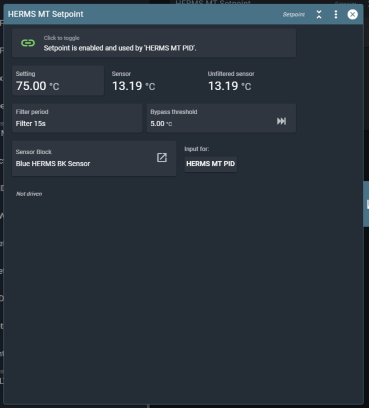
I am attaching a screen-dump of the MT setpoint.
Do you have any suggestions about why the integrator didn’t work?
No. Export your blocks while it doesn’t work. And make a screenshot of the pid and it’s graph.
We don’t have much info to go on now.
Hi again
Here is, hopefully, the info you requested. The red temp sensor is in the HLT kettle and the blue sensor is in the mash tun kettle.
As you said, these data are taken while the process is running and the integrator is not functioning.
Please let me know if there is more I could send you.
Blue HERMS BK Sensor.json (286 Bytes)
HERMS HLT Actuator.json (282 Bytes) HERMS HLT PID.json (1.3 KB) HERMS HLT PWM.json (455 Bytes) HERMS HLT Setpoint Driver.json (595 Bytes) HERMS HLT Setpoint.json (679 Bytes) HERMS MT PID.json (1.3 KB) HERMS MT Setpoint.json (660 Bytes) Herms Setpoint Profile.json (581 Bytes)You don’t have to export all the blocks separately. You can choose export blocks from the spark service page on the top-right menu.
This is a bit of a gotcha. I think what we are seeing here is actually anti-windup.
The target for the HLT is not reached (because you have HLT Ti set to zero it gets stuck under the setpoint).
Because the HLT is not reaching its target, anti-windup in the MT PID prevents the HLT target temp from increasing further.
I would try these settings (what I use in my setup):
HLT:
MT:
Another recommendation is to have as little water as possible in the HLT. Just enough to submerge the coil.
Thanking you so very much!
Thoughts around anti-windup have been here.
It is an enlightenment for me to see that conditions detected in the HLT PID domain have influence on the MT PID domain. Seems very good!
And yepp!, I will try out your recommendations.
Thanx and cheers.
Do we have a possibility for monitoring anti-windup?
No this is not logged. I’ll see if that’s possible.
I set the parameters you suggested. Yesterday I ran a step up to 68 deg. It didn’t seem to want to come any closer than 67.19 deg. I would expect the integrators to pull it up. A high Ti value should mean that I would have to wait longer.
Before I start fiddling with the parameters, it would be nice to have a sanity check of the system. I you would, what data should I send you?
Incidentally, do you see a possibility for anti-windup monitoring?
Export your blocks from the spark page, top right menu, export blocks.
For both PIDs, share the graph of the block so we can see what the internal values of the PID are during the run.
What I am thinking of is adding a field to the PID that shows the integrator increase per second, which is P - anti-windup.
Run on Wednesday 27.10.2020
The MT I value has some steps that I do not understand.
graph-HERMS Graph-spark-one-downsample_1m (8).csv (19.4 KB) graph-HERMS HLT PID-spark-one-downsample_1m.csv (26.9 KB) graph-HERMS MT PID-spark-one-downsample_1m.csv (26.1 KB)
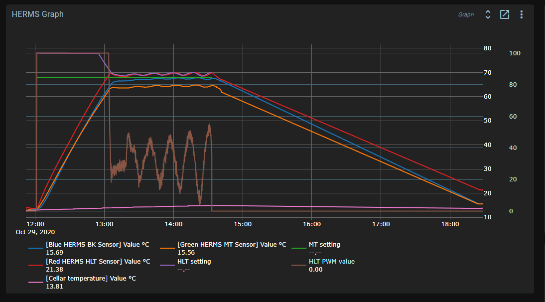
Run today 29.10.2020
The process is still running, until 14:30
brewblox-blocks-spark-one.json (20.4 KB) graph-HERMS Graph-spark-one-downsample_1m (8).csv (11.3 KB) graph-HERMS HLT PID-spark-one-downsample_1m.csv (20.1 KB) graph-HERMS MT PID-spark-one-downsample_1m.csv (19.3 KB)
Screenshots of the graph are a lot easier for me. You can also export the graph as image.
Yes, that’s helpful. I see that the setpoint for the HLT is swinging too much.
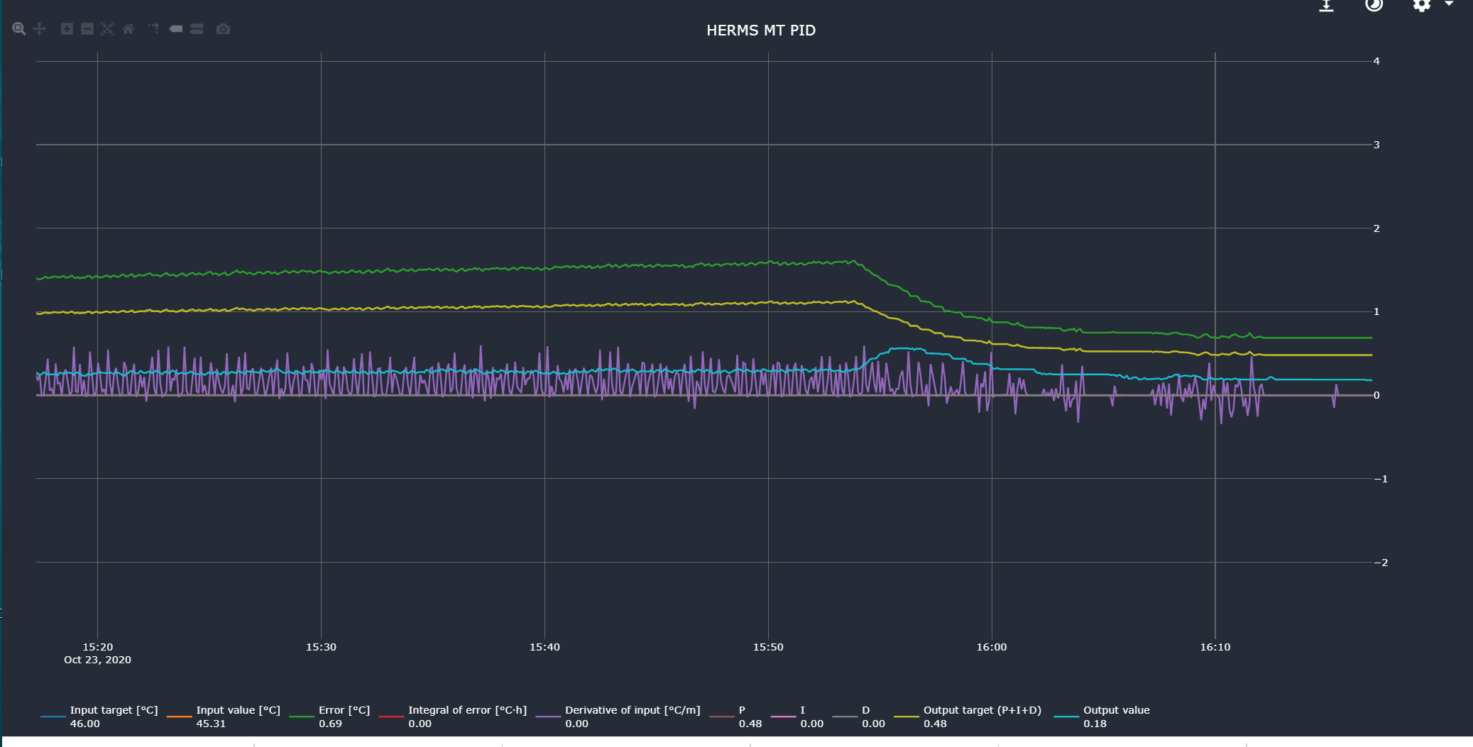
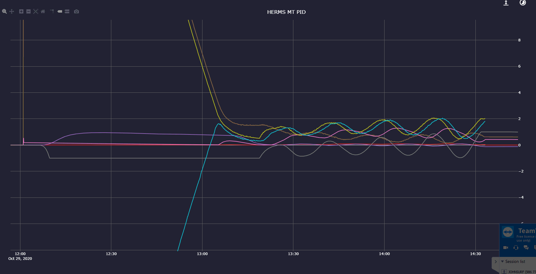
MT PID
You can see that the swings in the output of the MT PID have about the same shape as the D part.
The D part is too big. Try setting Td to 2 or 3 minutes instead. Or try with Td at zero at first, then if you have overshoot, increase it to 2 minutes.
Try making the integrator react a bit slower too, with Ti at 10m.
For the HLT, Td at 10 seconds results in a bit of a ‘grassy’ value, because of the bitflips.
Here you can also set it to 0, or set it to 1 min for a bit more filtering.
You can also set some filtering in both setpoints.
Your system seems to respond quite differently compared to mine. Do you have some photos of the setup? Do you recirculate the HLT with a pump to stir it continuously?