Built from a smallish old Zanussi Fridge/Freezer combo. It is 52-53 cm wide and about 120cm high. Got it for free from someone who had replaced the fridge in their cabin. It is hust big enough for my build and as small as possible to not take up too much space in my cellar.
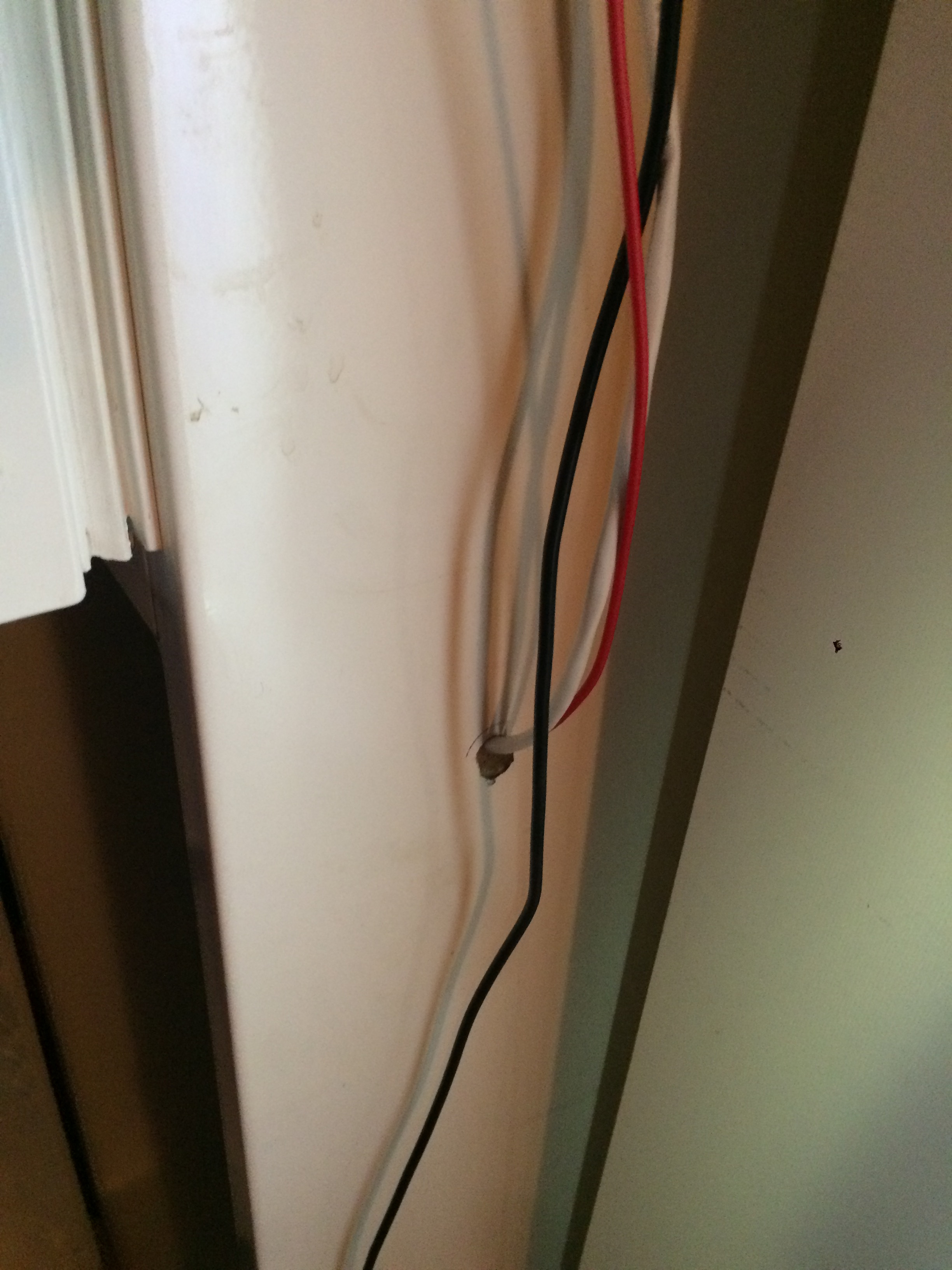
Running a wire through the wall. Old simple fridge with all cooling open in back and no danger of cooling liquid in the wakk (at least so I thought). 12mm drill
Network is run using Powerline from the apartment to the basement. Works just fine (as long as the phases as the same).
I am pretty happy, only downside is that with thhttps://community.brewpi.com/t/small-fridge-built-into-a-fermentation-chamber/2137/4e current prices of copper i ended up using some red wire I had lying about instead of bying propper red, black, blue, brown and yellow/green cable…
Just thought I should add a part list:
One fridge. Older is easier as running wires through the walls are easy if the cooling is visible in the back (take care still… Listen for noice. Check the internet)
One 60w tubular heater. They are great, waterproof and not too expensive.
One Raspberry Pi (preferrably with wifi)
One power supply for Raspberry - the 2A in the store works great
One high quality micro usb cable to connect the pi and the spark
One Brewpi Spark (with photon)
One wall mounted OneWire temp probe for the fermenter
One ordinary OneWire temp probe to meassure inside the fridge
One ordinary OneWire temp probe to meassure room temp (not actually necessary)
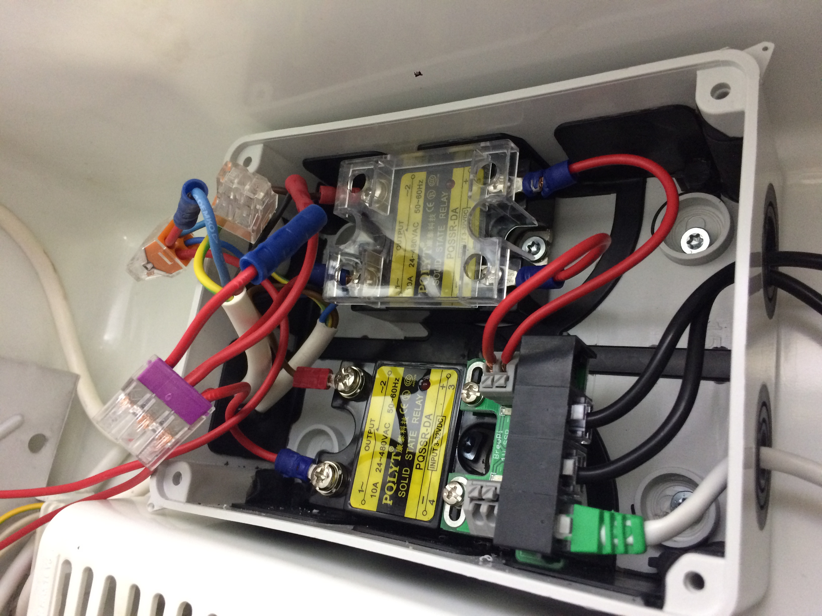
2 10A SSRs. One to switch the fridge. One for the heater
A OneWire SSR expansion board. If you connect the SSRs to this and the temp-probes inside the fridge. You only need one RJ12 (or RJ11) cable from the Spark and inside the fridge.
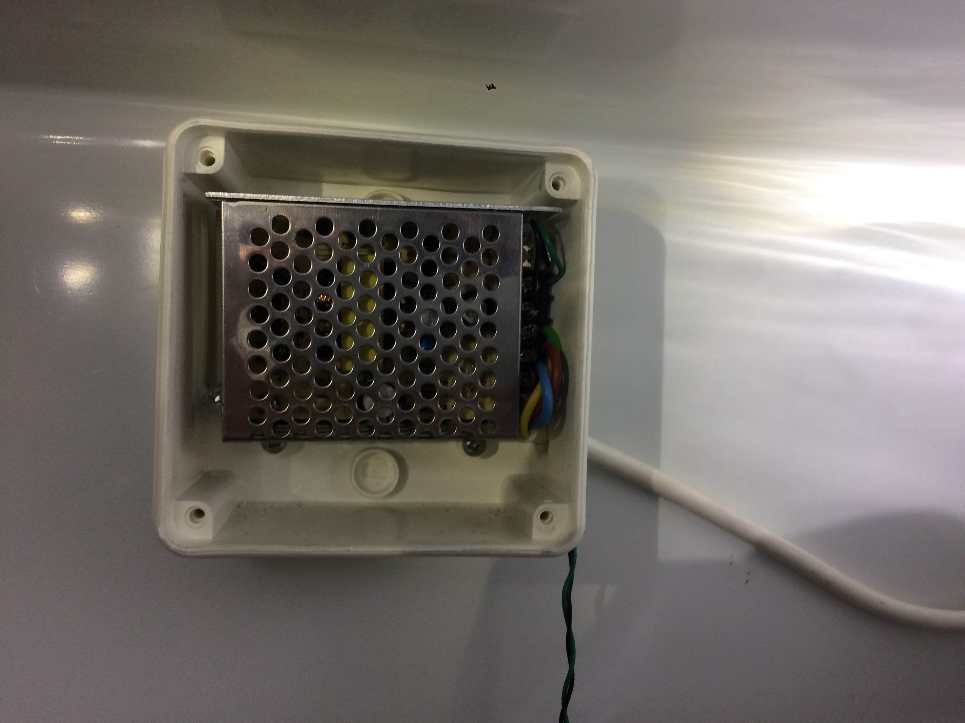
Decent transformer for the fan
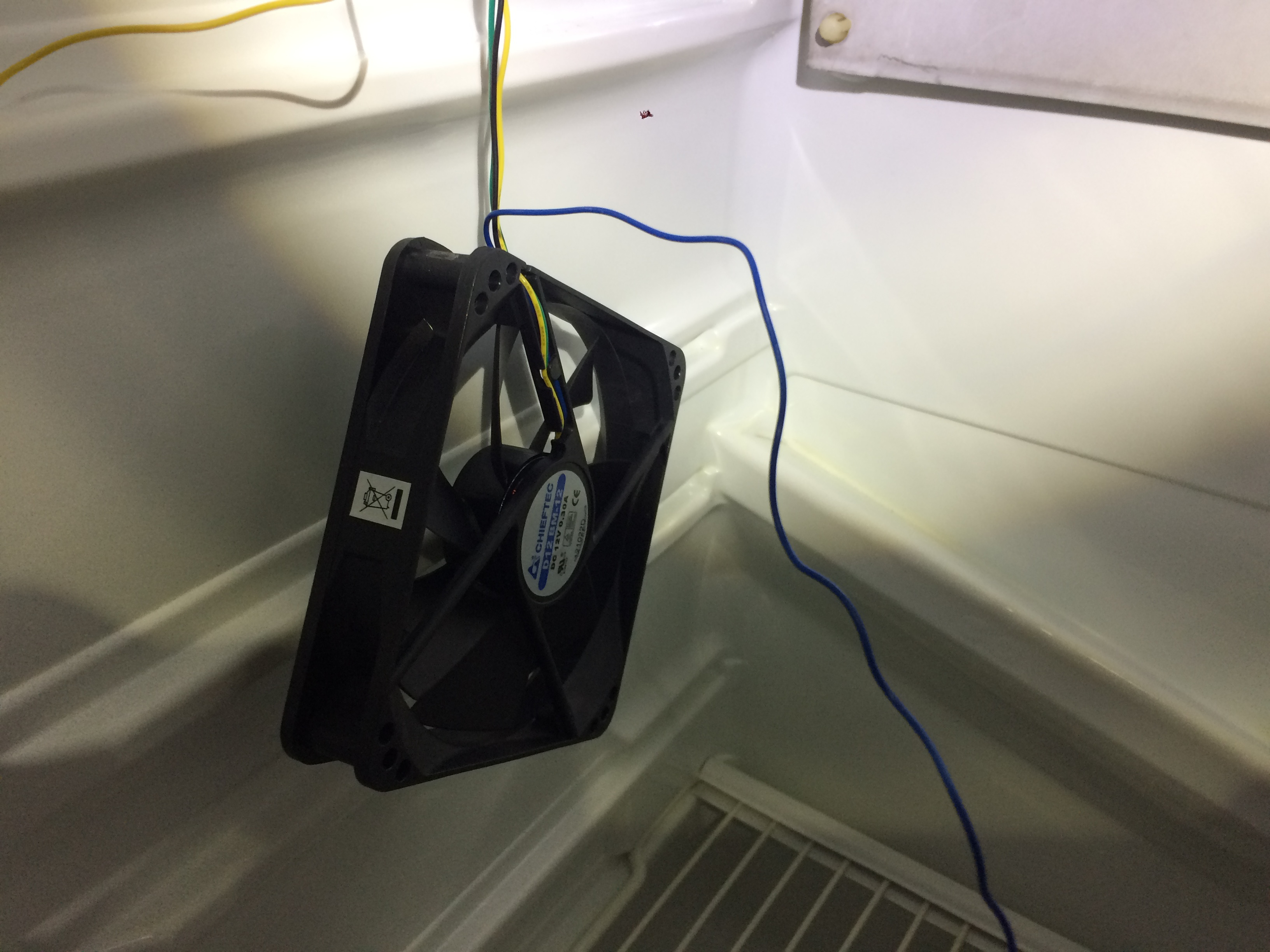
One fan. Look into the “hamster cage”-fans Elco speaks about
Some good connectors to connect the power wires. I prefer Wago connectors
Cable shoes to make connections to SSRs etc fit
well
One tool to crimp the cable shoes just right
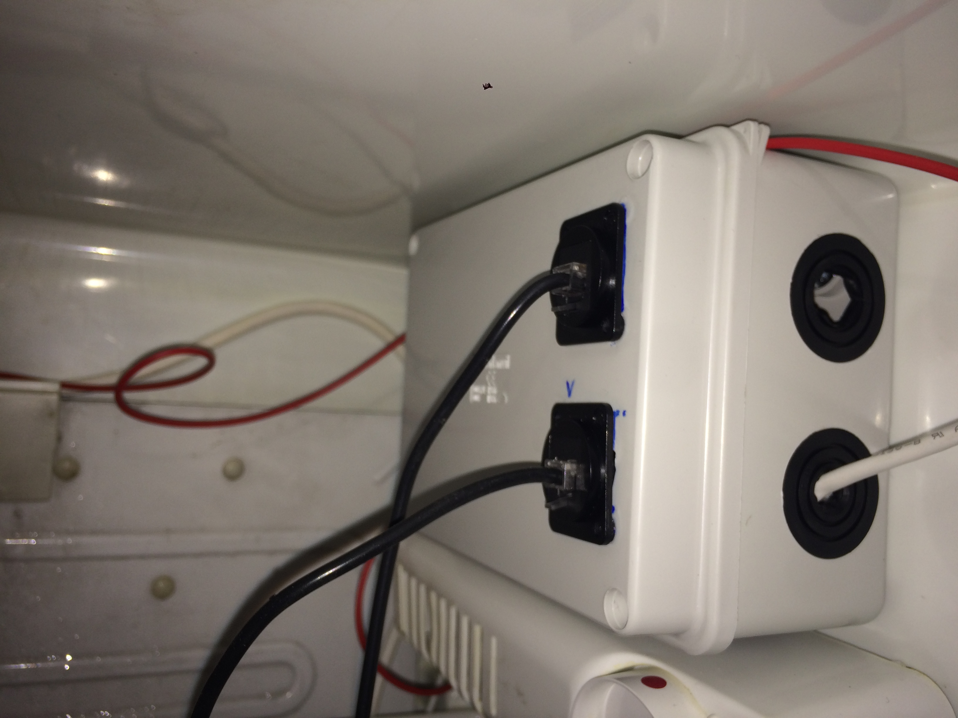
Water proof boxes to protect connecting cables, SSR’s etc.
Lots of cable
2 RJ12 panel mount coupler (in the store) makes connecting and removing temp probes easy
I used 2 30 cm RJ12 cables to connect between the SSR expansion board and the RJ12 panel mount coupler.
1 21mm hole punch to make the necessary hole in the fermentor
PS! If you only use SSRs and temp probes, you can freely switch betwwen RJ11 (4 wires) and RJ12 (6 wires) as only the middle four leaders are used.
I think I remeber all the parts. If there seems to be something missing, feel free to add to the list
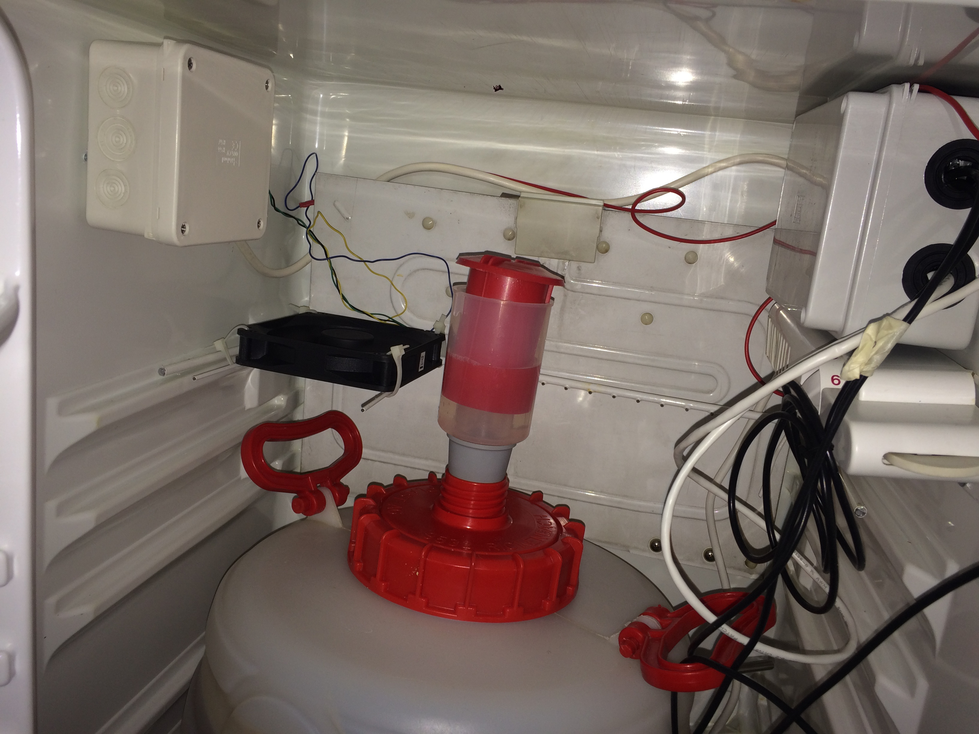
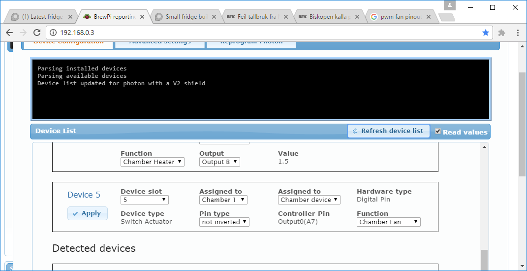
Doesn’t seem like the Brewpi is turing up the speed on the fan for the moment. It is turning just fin on 12v but the extra speed controlled by the brewpi is not kicking in. But, it is still doing the work of pushing the air around:-)
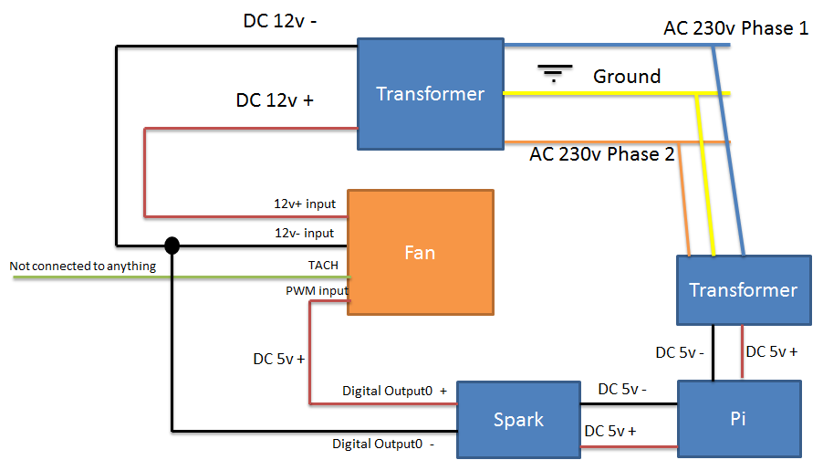
The fan is running continuously at low speed. The 12v connections ought to make that happen (and it is). After reading a lot of posts I thought this way to connect things would make the fan speed up when cooling? Adding 5v to the PWM pin should be the signal to the fan, right??? I assumed connecing this to what I guessed was the + part of the digital output was the way to go. I tried searching for “digital output spark” trying to determine if the left or right was the +5vdc, but found nothing. I found a picture with a red cable on the left so I guessed left equals +. Correct?
I think I do understand AC currents and DC currents, but I must admit than when it comes to electronics, I am not an expert at all. Still, I am very happy with the brewpi and I think it performs fantasticly. The level of support is amazing (I mean, you Elco, are online and helping out a lot! ).
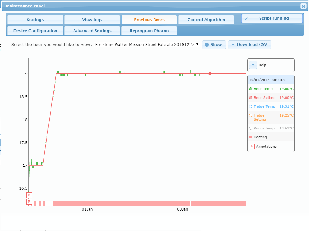
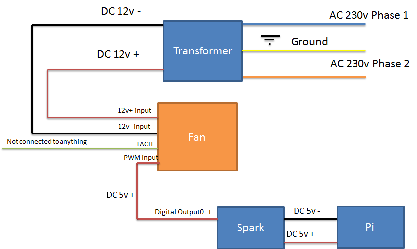
The meassurements, cooling and heating are working great. But I have not found any schemaics on how to connect a PWM fan on the site. So, this is my, perhaps faulty, attempt
The minus output (GND, 0V) is not the same voltage for both. So your 5V digital output is not 5V for your fan. To make sure both circuits have the same reference level, you need to connect both grounds together. The easiest way would be to use the - output on the Digital output 0 connector and to connect it to 12V- of the fan.
New schematic tested and working great. Now I can speed up and down the fan i test mode. I can also turn it on and of setting the output as a manual actuator. I can also set it as a fan and I hope that this will make it go faster whenever It is cooling


 ).
).
 Thanks