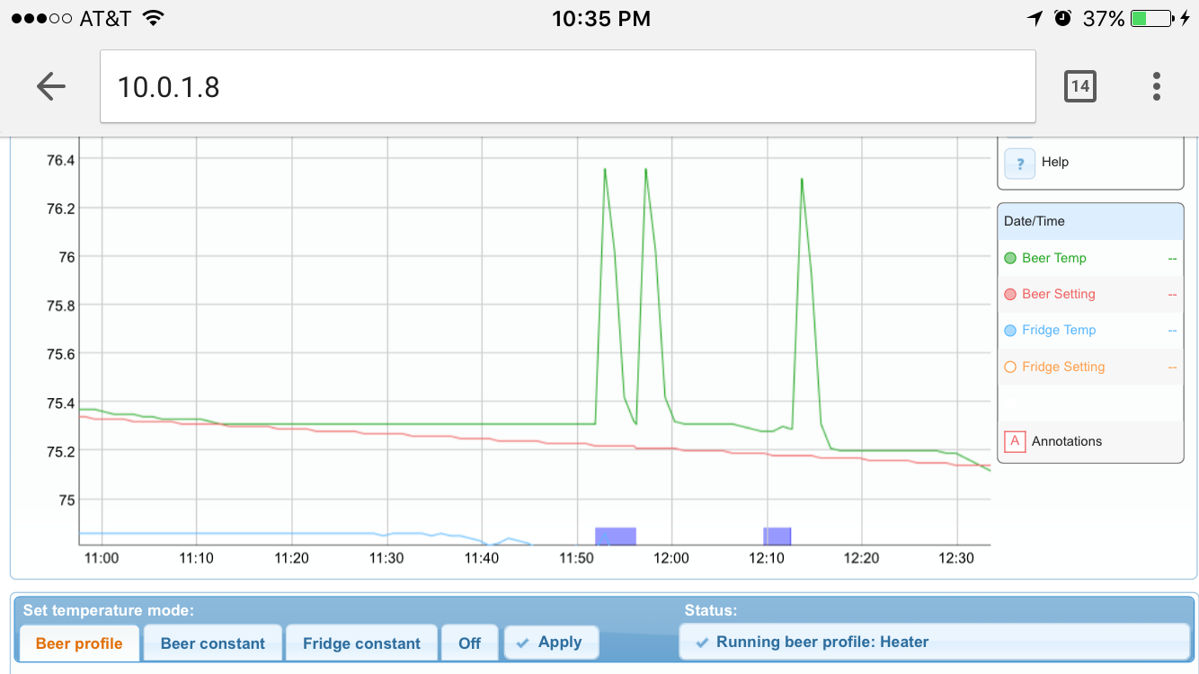
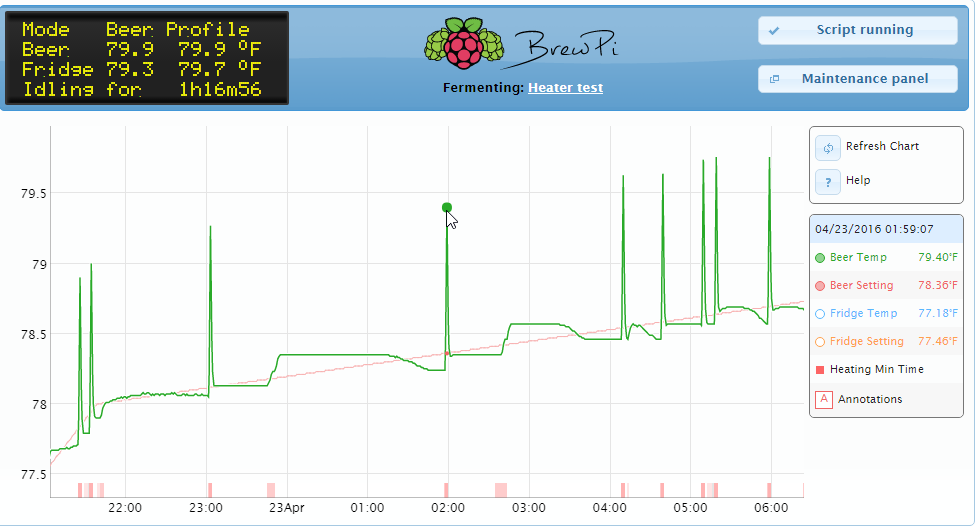
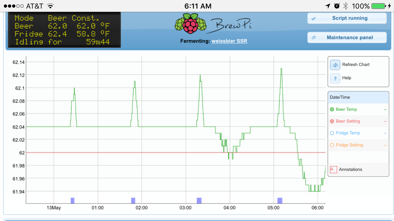
Hello! I have my brew Pi on a Pi 2 with Audrino. This has been working great for a few months and I love it so much. I am having s few issues with my temp variances and would like to dial it in. All my settings are default right now. You can see I’m having a 1 degree variance and would like to tighten it up.
I am logging every 10 seconds, which I am unable to change. When I change the intervals and apply. If i open setting again it is back to 10 seconds.
I am using chest freezer with SS fermeter with thermo well in front side for beer temp and ambient fridge inside. I am using a 40w fermwrap for heating.
Here are my settings currently:
PID KP 5
PID KI 0.25
PID kd 1.5
pid maximum 18
integrator maximum error 0.9 F
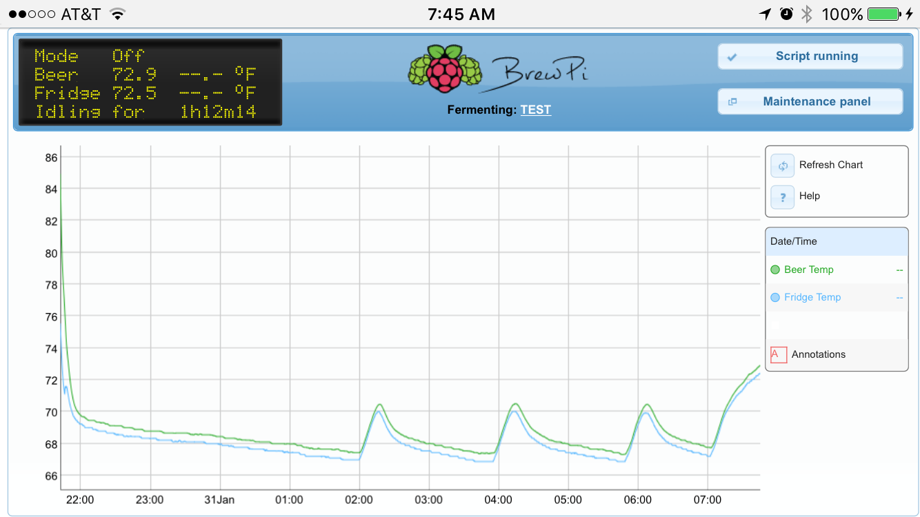
I don’t think so. At that time I did not have a heater. I only assigned the cooler outlet spot and relay. I then waited for it to kick into cooling mode and my fridge turned on.
But I would avoid Fotek. I have heard too many stories of failed Fotek relays.
You heater is probably not a problem, because it is low power and not an inductive load.
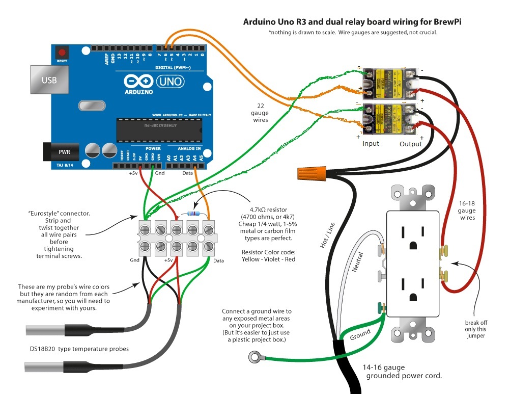
Hooking up the SSRs is very simple: minus goes to ground, plus goes to a digital signal pin.
And I can still use this with my current Audrino setup? So I just buy 2, 1 for heater and one for cooler? Also with the SSR I don’t need to use inverted pin setup like I currently am using with mechanical correct?
With my setup and using SSR what would the red wire I believe it says VCC shown in diagram above going from relay to terminals go to on SSR if it just has the ground and digital.
Thanks for all the help so far.
Perfect. I ordered some of these up. I will test it out and get back to you. My one other question for now is how come I cant change the logging seconds. If i change them and hit apply, when I open the menu back it is set at the default.
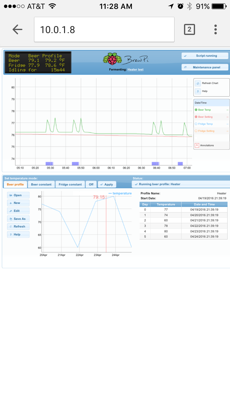
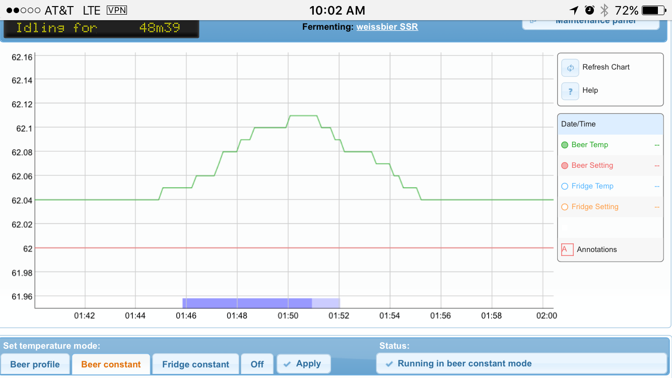
i got the SSR hooked up the spikes seemed to be resloved. will let run and see. the one thing i noticed was when i put a outlet test into the socket when the relay is turned off. It still lights up faintly and flickers tiny bit. and then when the relay is ON fully the socket tester lights up full power. Is this wired up incorrectly or is this normal? also the tester indicates correct wiring.
The SSR when OFF also has a very high resistance, but not infinite. It will let through a tiny bit of current. Because the socket tester only requires a tiny bit, it still glows faintly. This is nothing to worry about.
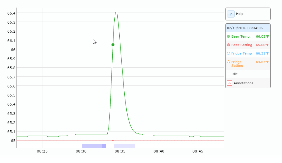
Are you sure the spike is caused by the cooling or the spike caused the cooling?
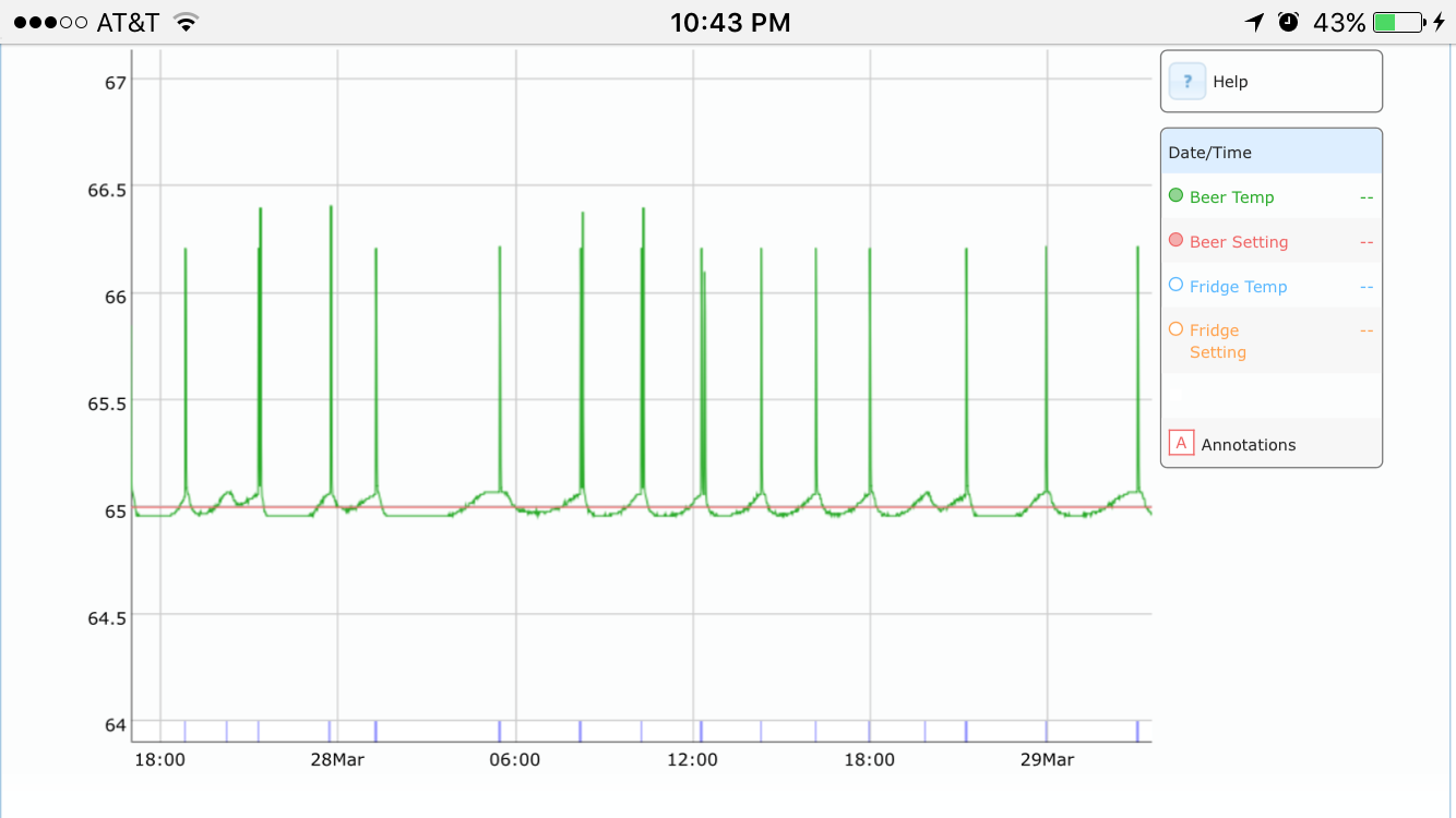
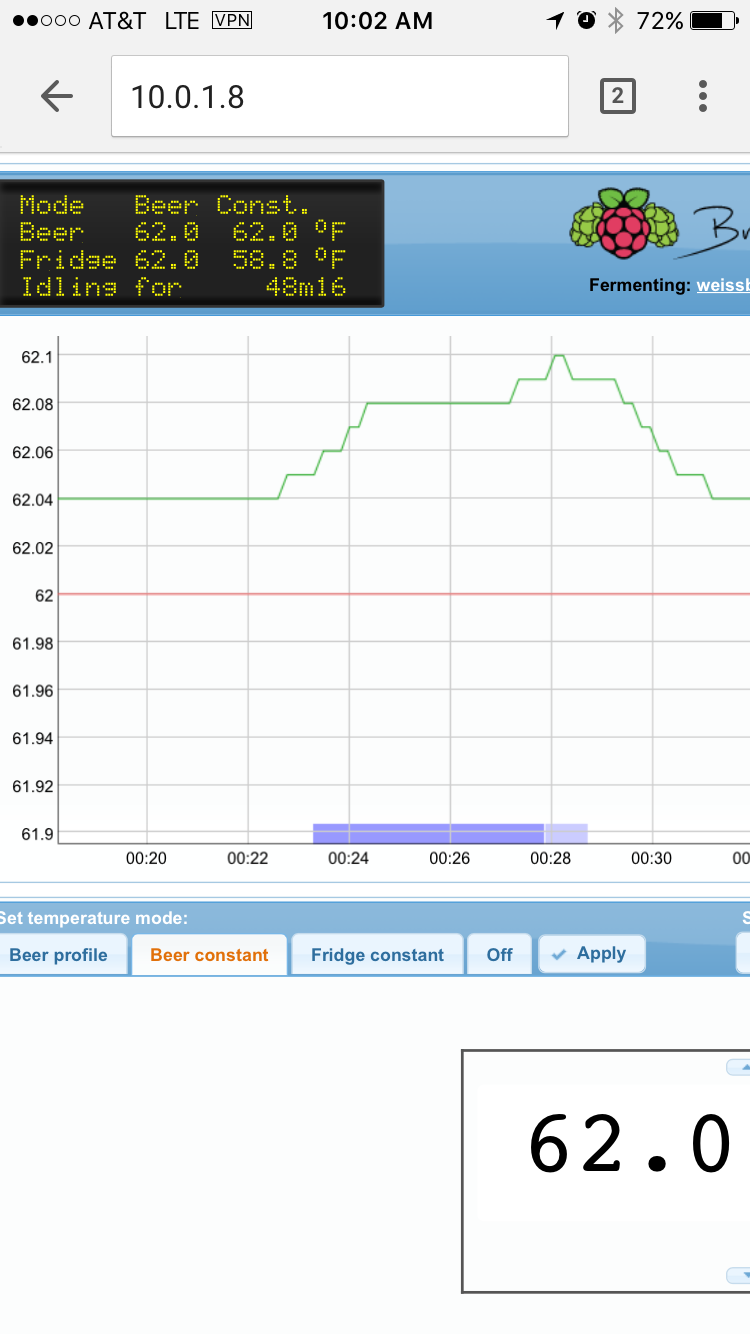
The spikes are not higher then 1 bit of the sensor, so it could just be a normal bit toggle. Zoom in more to verify.
At first, you had a huge spike of more than a degree, these are not higher than 0.06.