In an ambitious mood, I ordered the brewspark, couple of sensors and some SSR’s.
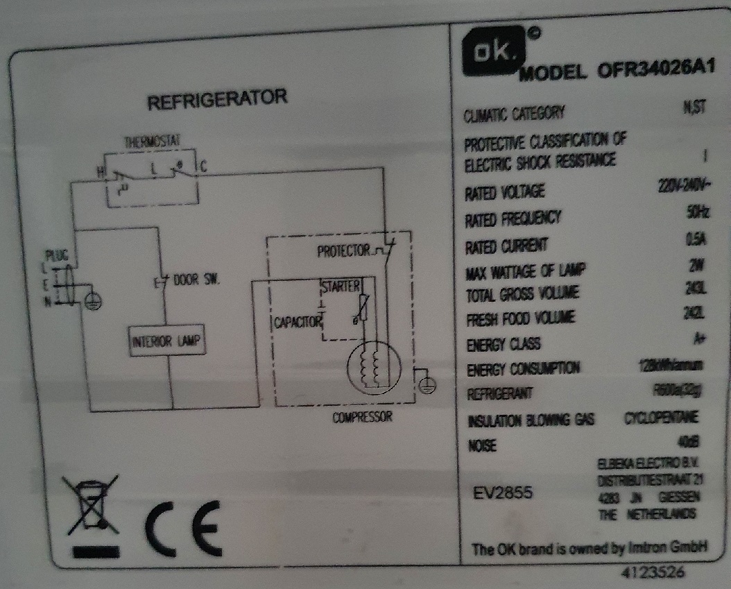
Went to MediaMarkt, for the Dutch among us, bought the cheapest fridge (OK OFR34026A1) they had and shelved the whole thing for about a year. Per my usual MO…
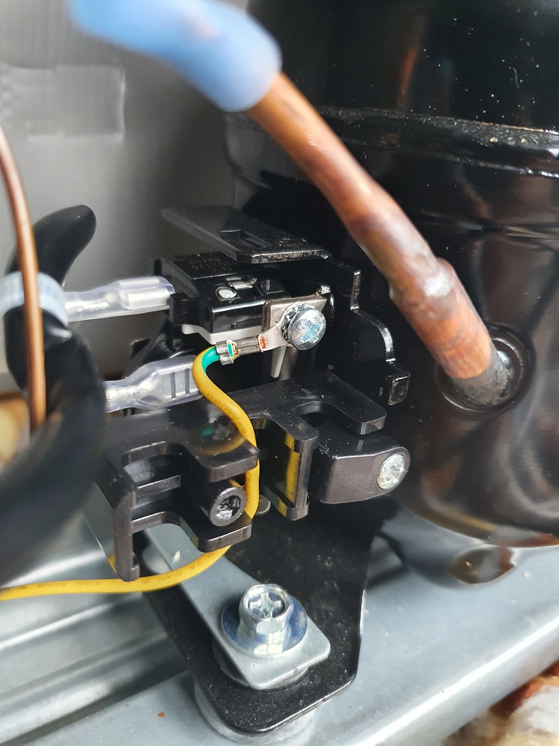
Cut to today, and lo and behold, when using the fridge hacking guide, it seems my compressor is missing a couple of wires…
Now, according to the wiring diagram on the fridge, the starter relay, the capacitor, and the wiring for the light is all there. I suspect the manufacturer tucked it all neatly away into the side of the fridge.
The thing I am most anxious about, is the live feed to the compressor from the thermostat, and the L feed from the power cord.
From what I can tell, there is just one (1) pair of wires going to the compressor. The blue/neutral from the power cord, and (what I suspect) the feed from the thermostat.
My main question is:
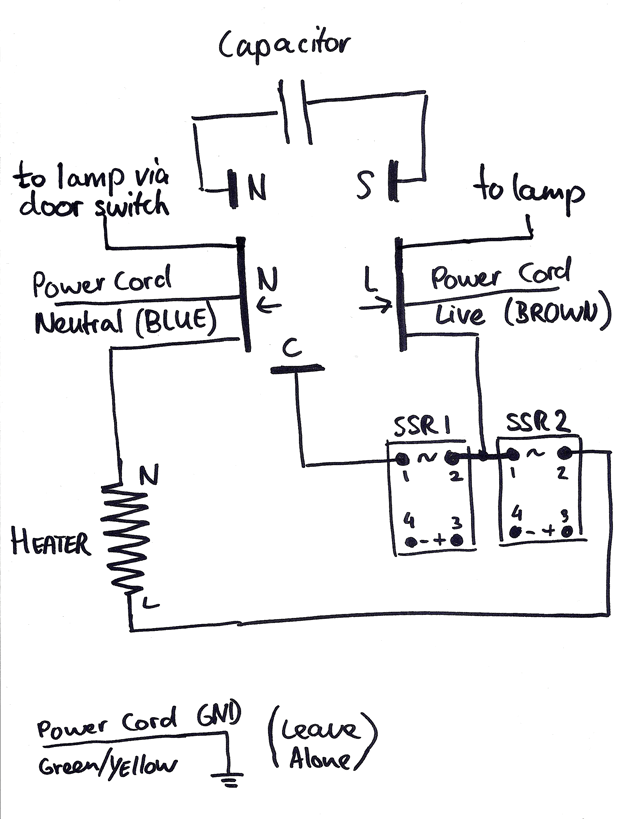
Am I correct in assuming that the grey line, is the one I need to attach to the SSR to control the compressor?
That would be the “C” in the guide diagram.
You should connect the SSR between L and C, replacing the thermostat in the schematic.
I think the grey wire is probably the wire coming back from the thermostat.
I can’t really see it in the photo, but my guess is your compressor has 3 wires:
Protective Earth (PE), aarde in Dutch, yellow-green.
Neutal, blue, connected directly to power cord.
Grey, live after being switched by the thermostat.
So brown -> thermostat -> grey at compressor.
You now want brown -> SSR -> grey at compressor.
Hi Elco,
Thing is… What is “C” when looking at the pictures?
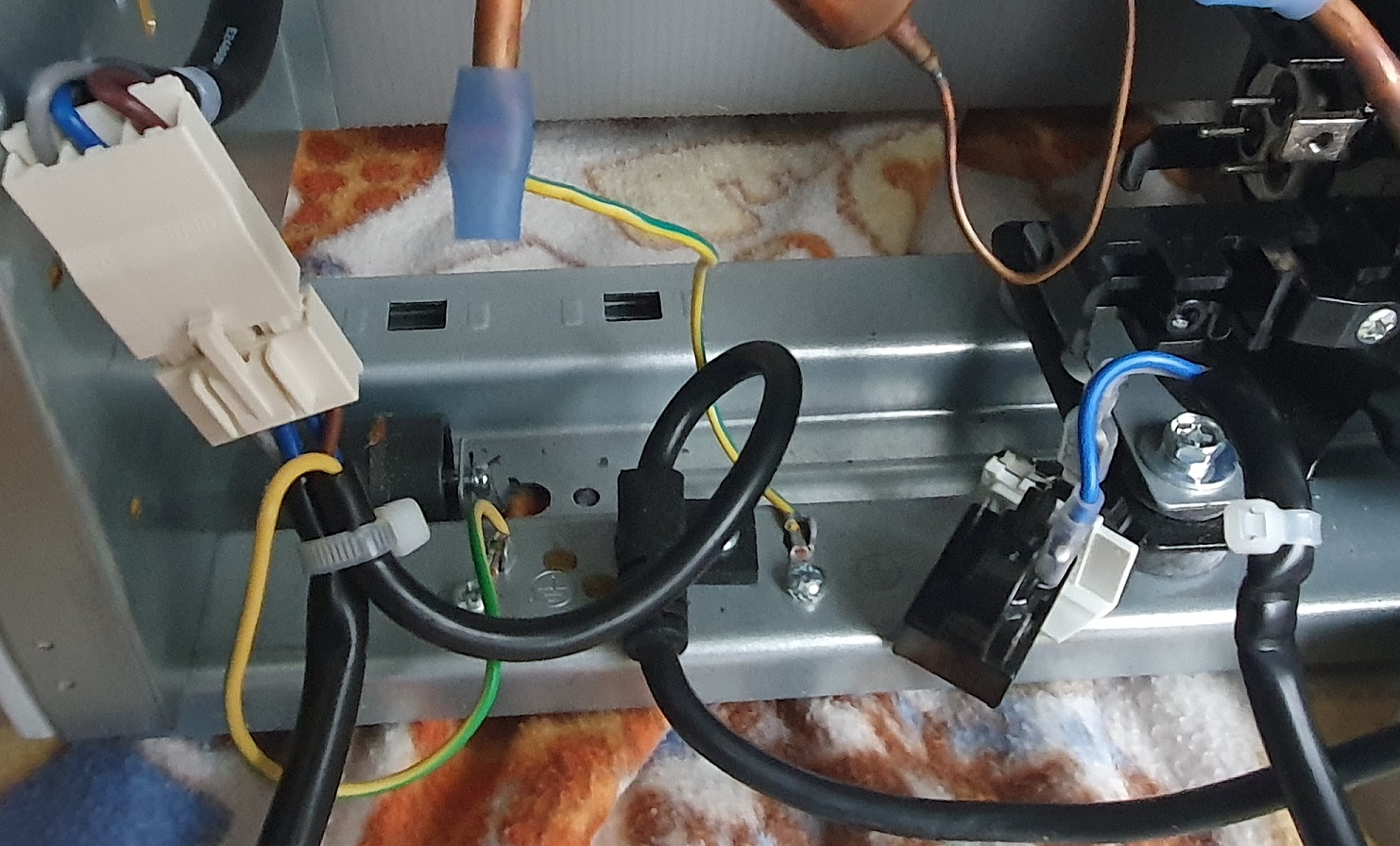
I have detached the wires from the compressor, as shown below at the following url: wires decoupled from compressor
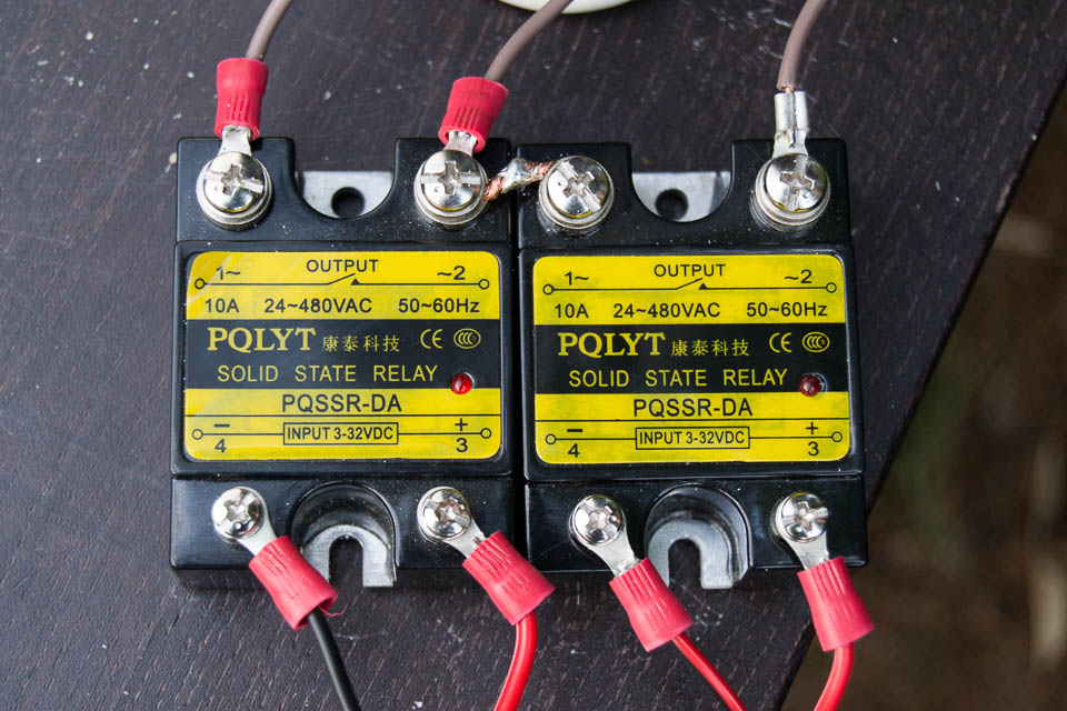
Hi Bob, yes correct, I have installed two SSR’s per the guide.
The description of that photo is: “Top: LIVE to compressor, LIVE in, LIVE in, LIVE to heater. Bottom: GND, cooler control, GND, heater control.”
In all my inexperience, I just connected the GND designated wires to the ground (green/yellow) of the fridge. But now I suspect, they should be the return of the wiring to the spark (in combination with the cooler/heater control wires).
Any thoughts on that?
‘Cause if what you state is true, I really have no idea on what to do…
