I have to say, really pleased with BrewBlox so thanks to everyone who contributed.
I use the same Pi and Spark combo to control the HERMS and then control the boil in the Kettle - it’s a bit of a faff with BrewPi but it’s worked really well. I have one ‘SSR control box power supply’ and have been switching between mashing and boiling by simply switching the power supply cable from the HLT to the Kettle and then tweaking the values in BrewPi. This seems a lot easier with BrewBlox but of course I have just one DS2413 output wired in to the single SSR. BrewBlox won’t let me have the same output widget assigned to the two vessels.
Question - can I wire both DS2413 outputs A&B to the same input of the SSR? In this case, if output pin A is ON, then output B would see that voltage and vice versa - will this spanner things? Or is there a more elegant solution?
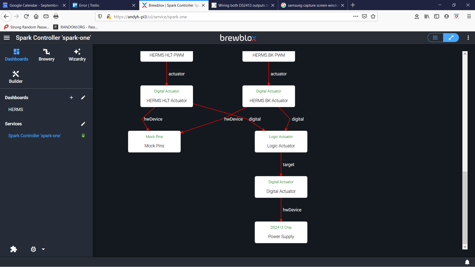
Solution 1: create a Logic Actuator that uses your kettle and HLT actuators as input, and a (new) digital actuator as output. The new actuator should have the DS2413 as target, and the two existing should target a channel on a (new) Mock Pins block. You can then OR the two actuators to trigger the new actuator.
Make sure the inactive control chain is truly disabled.
Solution 2: Create two Quick Actions:
one that unsets the HLT actuator target, and sets the Kettle actuator target
one that unsets the kettle actuator target, and sets the HLT actuator target
The first solution is more automatic: the DS2413 is triggered whenever either control chain wants it. The drawback is that you will get unexpected results when you don’t disable the “inactive” chain, and it suddenly enables the actuator.
The second solution requires you to apply a Quick Action whenever you switch outputs.
I think I’ll go with option 2 as that fits with the logic of swapping the cable and having to press a button to tell the software and is similar to (but a lot easier than) what I’ve been doing.
I’ll give it some thought and see if I’ve got it right.
Truth be told, I can’t get a Quick Action to make an Actuator block dynamically unset and change the target. The target is changed when I define the Quick Action but that’s all.
Ah yes, you’re right: setting actuator target in a Quick Action is still on the to-do list, as it involves multiple settings (target block, and target channel).
You can however, use a single Digital Actuator, and switch the PWM targets. Do check whether you also need to adjust constraints on the actuator (support for doing that will be released in a few minutes).
The DS2413 board has a pull up resistor and an active pull down. Pulling down twice might actually not be an issue.
The board is wired in such a way that the + pin is always high and the - pin is pulled down or not.
So while connecting two outputs to a single SSR is almost always wrong, in this case I think it would work.