So did you just snip the ends of your heater/pump and hook it up to a DC SSR to make this happen? I should probably just get some DC female pigtails and be good to go.
I would get some of these and not cut in the pump cable:
Ahh yes, avoid the cable clutter. Thank you.
Just to keep the info consolidated, I’m going to be doing this soon with my new brewpi v3.
Would I be able to use the power supply from the FTSs? The output is 12v an 8a, is that acceptable for the brewpi?
I also got the pigtails I linked above so that I can have quick disconnects on the heater/pump as I move the chronical to a different location to fill it/clean it/etc.
I’ll try to get a photoblog up, although I always get caught up in the action and forget it!
Yes, you could use that 12V supply for BrewPi.
That power supply could power the BrewPi spark, the heater and pump.
You’ll let the Spark switch 2 DC-DC SSRs to switch the heater and pump on and off.
Excellent, thanks to your prompt service, it went from ordering on Sunday night, to in my hands tomorrow by 10:30am. The Rpi is ready via docker (no issues it seems so far), and I’ll have it running by noon.
OK, so I’m in action with the advanced settings in, temp sensors in, and SSRs wired up. However the SSRs are not actually powering on/off the pump, I can’t verify the heater right now as I have cold crash going on.
Just positive to negative on all ends, using the brewpi legend on the back for the +/- ports. I get a light on the SSR but no pump action.
Actually I just took a closer look and put the system in test mode. It turns on, yet then turns off shortly after that.
You should connect:
12V + --> pump --> DC SSR positve terminal DC SSR negative terminal --> GND
The pump is driven with PWM, so it is normal that it turns on and off. I run mine with a 10 minute period and it only has to turn on for a few seconds every ten minutes.
Perhaps I’m missing something.
I have…
Brewpi is powered from a 12V PSU
+/- leads from brewpi to the +/- inputs on the DC SSR
- output on DC SSR to pump
- output on DC SSR to a ground
No action still…
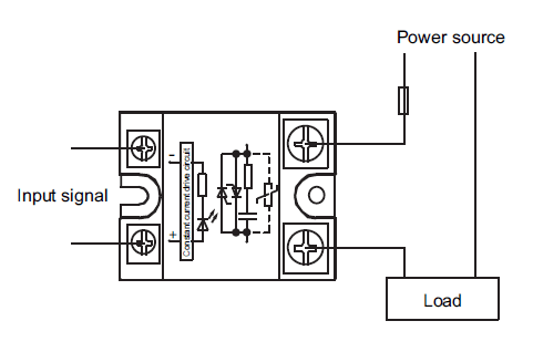
The SSR is a switch. It doesn’t supply 12V to the pump, it makes or breaks a connection.
So picture your 12V supply powering the pump directy, cut a cable and insert the SSR there.
Your Spark will not power the pump. Power to the pump is external, the spark just controls a switch (the SSR).
Sounds good, I don’t know why I couldn’t remember this from my other brewpi. I will make the change right now.

Working good now, it also helps to monitor the glycol cycling.
So I used the pigtails I linked to above, and then I used some wire nuts and made the connections between the two SSRs. It all worked out very well once programmed and wired correctly.
It was nice to be able to use the old FTSs power supply, and then I used the cooling only FTSs power supply to power the brewpi. Nice that I didn’t have to by anything but those pigtails to recycle some old parts.
I’m using wifi on both the pi and brewpi, and that has been performing great as well.

Slight issue occurred, I was ramping up and the heater will heat, but the SSR light basically just flashes every 2 seconds or so. As such, it’ll be in heating mode for 24+ hours. Any advice?
I have it wired the same as the pump which works normally.
Is the temperature correct? The default pwm period is 4 seconds. If it only needs to heat 10%, you’ll get a 0.4s flash every 4 seconds.
You can increase the period in advanced settings if you want. If it isn’t heating enough, increase heater 1 Kp.
Yes, the temps are holding as they should.
I increased the heater Kp by 1 and I notice it’s now running for longer periods of time. That helps to understand. And by the way I had it programmed, it was working exactly as it should.
Thanks for your patience, I can handle the coding fine, but the Kp, Td, Ti, etc are over my head.
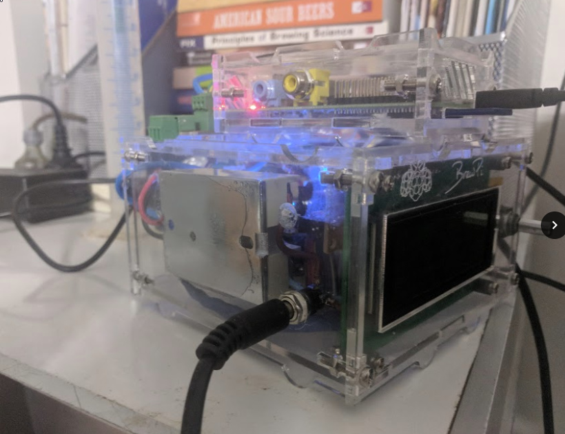
@boasist, I have the parts list and can see what has been explained/discussed in this thread, but do you have any photos of how this is connected and working together? I’m a much more visual person and maybe some pictures will help me connect all of the dots here. Thanks.
My question is kind or related to this post. I am trying to build a fermentation system to managed each fermenter (4 in total) individually. I just bought the Brewpi Spark v3 so I want to know if this is possible:
The idea is to design the following set up:
- A glycol tank in a hacked freezer with a pump recirculating through a pipe going pretty much in circles
- From that pipe, I want to put 4 solenoid valves to go to each of the jacketed fermenters (4 in total)
- Can the Brewpi manage each solenoid valve and each temperature so the valves open and close automatically in order to get the objective temperature in each fermenter?
That way, I can manage each fermenter tank individually and I can do Primary, Secondary, Diacetyl rest, lagering, etc within each of my beers.
Do you guys have any suggestion?
Thanks a lot!
Cheers
Not possible at this time. I am not sure where that comes in at in the timeline but this a future feature to be able to have multiple fermentations on a single BrewPi.
Cheers,
-Stephen
Does anyone have recommendations for using a ftss on a brewpi V1?
I’ve managed to incorporate the fittings into the brewpi housing, so I can just use a single power supply. And heating and cooling are working, but I don’t seem to have as many options for Kp Td etc.
Heating seems ok, but I’m getting a bit more overshoot with the cooling than I would like. I’ve been putting the ‘fridge’ temp probe under the neoprene jacket and have set Kp = 0, Ki =0 kd =0
Is there any way to limit the amount of time the cooling can be on. If I could set it to 20 second bursts I think it would solve my issue
The minimum cooling time is your problem. Glycol is so powerful that it will cool way to quickly. You will have to recompile the firmware with reduced minimum time.
The algorithm on the spark will handle this a lot better because it is PWM based.

