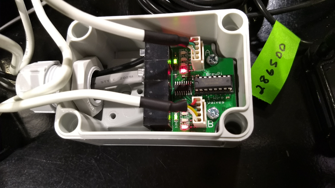
This tells me that power is coming through and the valves are connected and reading closed (which they are). All signs that indicate the previous board was defected.
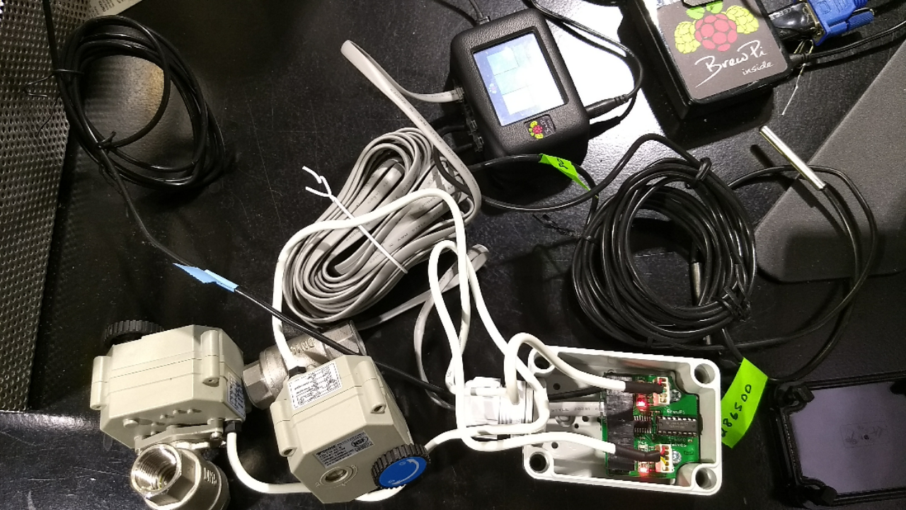
I’m running into an issue when the rj 12 cord is connected to the spark along with other sensors. In the picture below I have the expansion board with 2 valve operators and a one wire temperature sensor connected. The expansion board is connected to the spark which also has 2 additional one wire temp sensors attached. The spark is connected to the RPI.
When the expansion board is connected two things happen:
The temp sensor connected to the spark stops recording data. This was confirmed by unplugging the extension board and refreshing the temperature graph on the front page of the GUI. A gap appears during the time the rj12 cord was connected.
In the device settings the temp sensor that is attached to the expansion board does not register. The temp sensor does register if it is connected directly to the spark.
There is a 12v power supply connected to the spark.
Are you sure that the cable you have has the 2 plugs on each end wired identically?
When you hold the plugs next to each other in the same orientation they should be exactly the same, with the colors in the same order.
Another possibility that I could think of is that the cable is very long. Most phone cables are thin and have a high resistance per meter, that’s why the cables that we sell are made from much thicker CAT5e cable.
If they are thin, they will have more resistance per meter. If they are long, they have more meters.
Power (12V, 5V and GND) also goes over the cable. If the cable has high resistance, it is possible that the voltage at the board is much lower than 5V, because of the voltage drop over the ground cable.
In my own setup, I had a few issues with this too and switching to CAT5 cables solved it. I started selling them because I could not find really thick RJ12 cables, so I had them custom made.
They can ship in an envelope cheaply: https://store.brewpi.com/temperature-control/cables
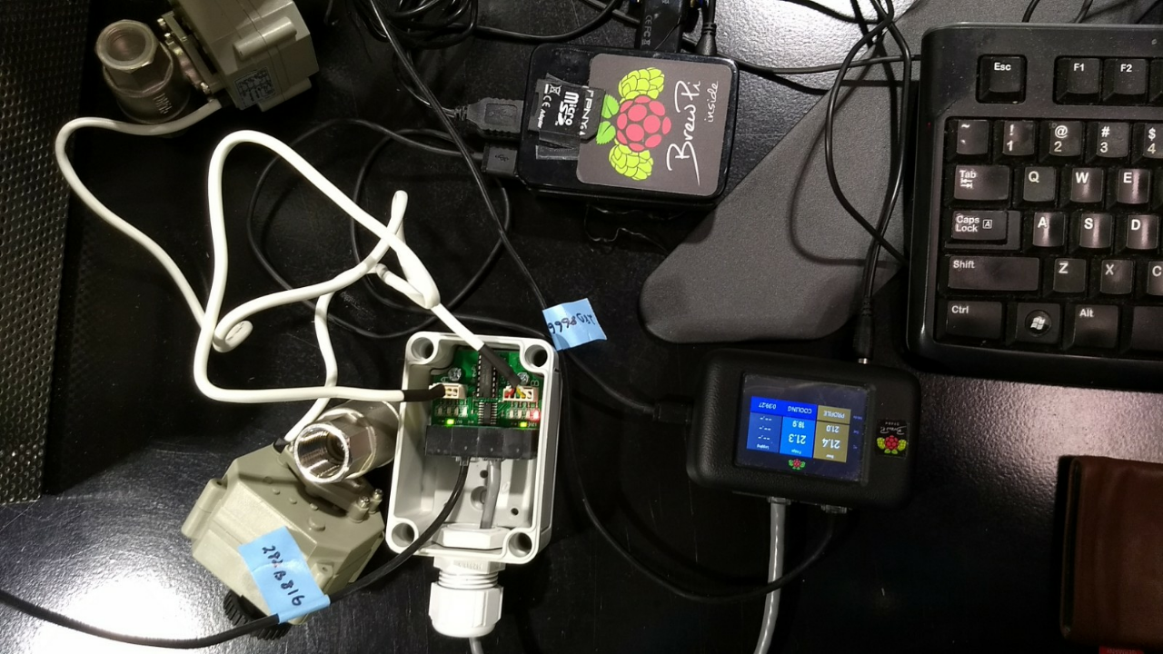
Ok. After a delay I’ve started working on addressing the expansion board. I order and received the shortest rj12 cable on the brewpi website. Upon setting up the RBP, spark, and expansion board I connected 2 temp sensors and 2 electronic valves to the expansion board. It’s illustrated in the picture below.
It successfully is able to support the temp sensors on the expansion board and record data. Thanks Elco for your troubleshooting help.
Now onto the next part, getting the electronic valves up and running.
There seems to be 2 issues at the moment with the valves.
As you can see in the picture only one of the valves is registering open/closed. When working with the gears on the manual adjustment setting it feels like the wheel is slipping and there is a grinding noise. After some manipulation the both register being open and closed. Are the gears metal or plastic? Also, can the gear box be accessed through the screws. Just wanting to understand how to open and proceed it before I start. Ideas?
In recognizing the values through the web GUI, I setup the manual attenuator setting but have not been able to digitally control the valves. Previous postings suggest it may be possible, but there doesn’t seem to be a definitive way. Not sure where to start on this one. As mentioned previously, I want to set a temperature parameter, have the temperature probes monitor the liquid. When the liquid needs to cool down then, the valves would open and control the profile.
Yes, you can open the box and access the motor/gears. I’ll have to open one myself to see what’s inside. The manual override is not directly connected by gears, only when you pull it up, it will connect to the motor.
To be able to assign a valve as heater/cooler, you have to be running the latest version of the web interface, published 2 months ago.
I’m on version 5.2 for the spark using the command: sudo python updater.py. Is there a seperate update for the web interface? If so, what are the update commands?
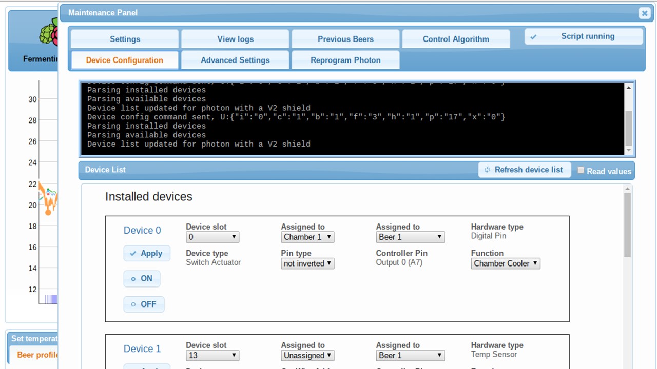
Below is a shot of what I see on the maintenance panel --> Device configuration page with the installed devices if the update is correct
So from what I can see, the spark is registering the valve (or at least appears to be), but pressing the open or close button on the GUI does nothing (both with and without hitting the apply button). Is there something I’m missing?
Also, does the position on the expansion board matter? If the valve has a one wire address that is unique, I would presume no. Why the output choice of A or B?
I’ve been troubleshooting the valves over the weekend and can get both to be recognised by brewpi, but they both have the same onewire address. See below.
The valve control boards have two outputs (A & B). Same with the relay control boards. So same address is normal. Not sure why your valves aren’t working though. Beyond my knowledge.
Thanks @j616s for the clarification on the valve outputs. I’m still having trouble getting the valves to open and close. Maybe it’s me, but is there more to just pushing the open and close buttons on the device list? I’ve tried a couple of configurations and the valves won’t move. Is there an initial configuration that first must be performed before they’re operational? or is there something else I’m missing?
I can just about see in the background of some of your images that beer profile is selected on the main page. I imagine you’ll need the temp mode to be “off” in order to manually open/close valves? Other than that, things look sensible. Does the valve control board have LEDs on it like the relay control board so you can check it’s got power and that it itself thinks its opening/closing valves? Might narrow down your search a little.
Thanks for the suggestions @j616s. I tried turning off the temp mode but I still cannot digitally control the valves.
Here’s what I can see and have verified:
The extension board is connected to the spark and is powered (the 5&10V green lights are on)
Temperature sensors connected to the extension board are recognized by the spark and can be seen on the brewpi GUI.
Both valves manually open and close and the LED lights on the extension board follow the corresponding open/ing close/ing position
The valves are recognized through the GUI on the brewpi system (see ablove post)
Here’s what I don’t know:
The correct digital configuration to activate the valves (i.e. control the valves from the brewpi GUI) (temp mode off?)
How to control the valves from the user interface (only control through open and close buttons or have to hit APPLY after selection)
Here’s what I want to do
Setup the valve system with a heated or cooled liquid to work with the temperature profile digitally to control liquid that is monitored by temperature probes
an example (I realize there are simpler ways to do this, but it illustrates my point): mash profile starts, temperature sensors monitor liquid initial temp,valves open (if connected to hot water), temp profile gets close to mark, valves slowly close as temp sensors get closer to ideal, valves controls temperature using temp probes as guides.
At this point the evidence is pointing to a software solution. @Elco any other possible directions?
I have no idea whats changed that might have caused it, but I’ve just gone to check my fridge still works after changing the compressor mounts. Manually switching anything that wasn’t set as a manual actuator meant turning on/off with the manual buttons didn’t seem to be working even with the control mode set to off. Things are still working with the fridge set to do its thing, though. Only change that’d have an effect on this from my side is updating the firmware/software recently. I seem to remember there was an update recently to prevent the fridge set-point swinging wildly & the compressor/heater coming on without need just after a reboot. I wonder if that’s had an impact here?
Have you tried setting your valves to manual actuators to check them when manually switching on/off?
I’m trying to follow what’s happing here, but it’s a bit unclear to me.
Can you give me a simple test case describing what you set up and click, what you expect to happen and what actually happens?
I think @mashctrl is just struggling to get the “open” and “close” buttons in the control panel to actually do anything at all to prove their valves are working.
Just troubleshoot the next piece of the puzzle. Thanks @j616s for providing thoughts.
As stated above, I am not currently able to use the buttons on the web interface to open and close the electronic valves.
The setup
Connected the extension board to the spark and rbp (spark currently running 0.5.2)
2 temperature sensors (live and reading)
2 valves (everything is visible on the maintenance deviceconfiguration tab of the web interface)
-1 valve is assigned to output A and to a chamber cooler
- another valve is assigned to output B and chamber heater (both are assigned to chamber 1/beer 1) The tenth post on this thread has a picture of the screen I currently see
Both valves are in the closed position (verified on the web interface, both are lit red on the expansion board and are closed upon visual inspection)
The temp control is currently off on the main web interface
What I expect to happen
I expect that if I click open or closed on the valve control in the maintenance device panel, the valves will respond.
What actually happens
When I click on the open valve control button for either valve on the web interface I see no response from either valve (i.e. the valves don’t open or lights on expansion board changing)
When the valves are controlled by the PID (set up as heater/cooler) they cannot be manually toggled. The buttons should be disabled to clarify that.
I actually discovered a bug in the communication with the valves and will try to create a new release before Christmas to fix this and improve reliability.
Does this mean that 2 temperature probes have to be assigned to “beer temperature” and “frig temperature” for the valves to work and temp mode created?