I am still new using BrewPi by that reason I have a question on the Maintenance part of the web interface.
Are there any particular order the temperature sensors to be assigned i.e. room,chamber and beer temperature as device slot 0,1,2. Will this order work with the script.
Are the green connector on the BrewPI Spark meant to used to control the SSR Expansion Board? I will be using the expansion board to control the SSR’s installed inside the fridge, since only one wire is needed from the BrewPI Spark into the fridge then.
Are the control wire between BrewPI Spark and the expansion board passing through the RJ12 connector, or through one of the grey connectors on side of the expansion board.
Are there any particular reason to control a fan inside the fridge. It should be running at all time during fermentation I think. I am having the heat conductor together with a fan installed at the bottom of the fridge. The fan is insuring stable and uniform distribution of chamber temperature around the fermentation tank.
The order doesn’t matter. Sensors are used by address.
The green connectors is for connecting SSRs directly. If you use the expansion board, it is plugged in the RJ12 connectors that are also used to connect sensors.
One cable between Spark and extension board. Sensors can be plugged in either Spark or extension board. Everything is just linked together.
Yes, I would run the fan at low speed continuously.
Hi Everybody
Elco, thanks for your fast reply to my previous question.
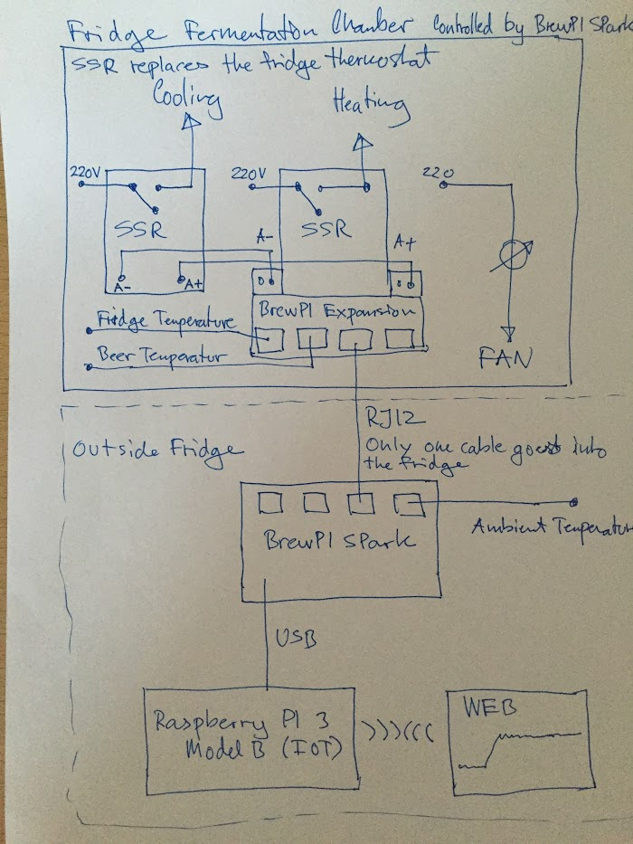
I have prepared a simple connecting diagram between BrewPI Spark and the fridge, using only one cable between BrewPI Spark and the fridge SSR’s. One of the SSR’s in the fridge is provided with SSR Expansion Board.
Please verify the connections shown on the diagram.
My questions mainly concerns how to configure the WEB Maintenance/Device configuration, in order to use the cable that connects BrewPI Spark (RJ12) to the expansion board in the fridge?
Another question concerns how to address the RJ12 outputs on the expansion board from WEB Maintenance/Device configuration?
I am still not completely confident on configuring the web interface in accordance with the connecting diagram, so please advice on that.
I really appreciate response from everybody in the community
All sensors, and the SSR expansion board SSR outputs are found based on their address.
There is no difference between any of the expansion board RJ12 slots and those directly on the Spark. It is one big address based bus.
Your schematic is wrong for the SSR expansion board. Grey connector A is connected to the slots on the board. Connector B goes to the second SSR.
Hi Elco,
Now I think I understand. The grey terminal to the left is internally connected to the terminal pads marked A- and A+, and only used for wiring purposes, in case that the expansion board is not installed on top of the SSR. The grey terminal to the right can control one additional SSR, like shown on wiring diagram I.
It also make sense, when reading the input below from bill
I’ve got some DS2413 chips and am interested in DIYing my own expansion board. Are the schematics at https://github.com/BrewPi/ssr-onewire-board the latest revision? I’m having trouble figuring out which pins of the RJ12 (coming out of the BrewPi Spark, towards the DS2413) need to be used.
I have just pushed the uncommitted changes I had, but I think they’re irrelevant for a DIY board.
The pins used on the Spark are 5V Ground and Data. The pinout is printed on the bottom.