Troubleshooting temperature sensors

Thanks Elco for your quick reply.

After posting this entry, while eating breakfast I realized there was one place I did not check - I have wiring routed through the walls of my freezer. I’ll tear that apart and check everything inside there as well.

I think I will order new sensors. While I would love to support your operation, being in Canada, unfortunately your store seems a little pricey for me and finances are a concern. When the new ones come, I’ll add some waterproofing around the shrink wraps in case condensation is getting in there… Maybe some glue and extra shrink wrap. I am using a thermowell in the beer but condensation is still a concern.

I’ll try the above and keep the thread posted. Thanks for your help.

I was sitting next to the fridge all day and it seems that it does crash when the fridge kicks in. I missed this earlier apparently because I was not zooming far enough into the interface:

So, in addition to the sensors being possibly broken, my mechanical relays are suspect yet again. I will order one FOTEK SSR from Amazon for the fridge, as the mechanical seems to be okay for my 100W light bulb heater.

Three questions for anyone experienced

  • my mechanical relays are currently mounted right next to the arduino. I assumed this was okay, but moving it may improve my situation?
  • the fridge has its own relay in-line, which is built into a thermostat that is set to “always on”. Would bypassing this completely impact the inrush? assumption: no
  • I’m using a sainsmart arduino knock off… any experience with these being flakey?

Thanks again…

In fact, I think I will risk a double 5A SSR since they are reasonably priced here.

  • my heat source is 100W @ 120v
  • my freezer is rated at 1.30 amps based on the plate, so even with inrush I think 5A will be sufficient…

any words of caution?

Based on my own experience and stories of others, I would avoid fotek. There might be good ones and the bad ones might be counterfeit, but I would just avoid the brand.

The main benefit of an SSR is that it switches on a zero crossing of the AC current. It is not the mechanical relay that is causing the interference, it is the possibility of switching when the AC is at its peak. The motor and start capacitor have very low resistance at this point and a high inrush current will result. When an SSR switches on a zero crossing of the AC voltage, the current will slowly ramp up with the AC sinus.

Bypassing the internal relay in the thermostat is a good idea.

Sainsmart is decent, I have sold them in the past.

5A is probably enough, but don’t take my word on it. The SSRs should have a small heatsink.

We ship to Canada for about 14 euro.

Thanks Elco,
I think I will buy a dual Sainsmart 5A SSR. I can get these including delivery for $20 CAD even, which is about the same as shipping from your store unfortunately. I do appreciate the help and hope I can contribute in some way, as I have benefited greatly from your help and work.

I also see the point about the in-line mechanical SSR at the fridge needing to be bypassed, as even if I put the SSR that switches at the zero crossing, there may be a delay before the mechanical relay triggers, causing an in-rush.

Thanks again

UPDATE, possibly fixed.

TL;DR, my GND was connected to my fridge’s household earth connection, and disconnecting this seems to have fixed this problem and all my other interference problems.

The things that come to you while laying in bed trying to sleep… I was thinking about my wiring, and I realized that through wiring my sensors through the wall of my fridge, my GND gets linked with the house-hold earth line.

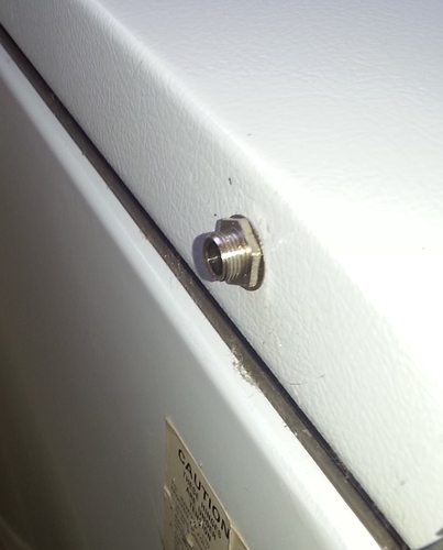
The frame of my fridge (including cover) is grounded well to earth. I drilled a hole to put my sensor connector chassis-mounted on the wall of the fridge, which has a screw-and-nut style mounting. At this point, the chasis of the sensor plug makes contact with the fridge chassis, thus connecting the two.

Again, not an electronics person here. I assume that the GND / EARTH coupling would not generally be a problem, but I can also see how this would propagate EMI into my system much more easily.

All my EMI and typical crashes seem to be fixed by bypassing that wiring temporarily. I will take that out, isolate it from the frame, and put it back.

Hope this helps someone!

Quick update - this indeed fixed my problem. I have received the SSRs but will wait until this lager is ready before swapping it out. The whole setup has been rock solid without even a hint of interference or lockup now for nearly 2 weeks.

Unable to detect temp sensors via Maintenance panel, yes probably something I’m missing but I have scoured the internet and not found the answer.
Script is running
BrewPi v0.2.10 build unknown, running on an Arduino Uno with a revC shield on port /dev/chamber1
I have measured voltage at sensor side of connector and get 4.99 volts
4.7K resistor between positive and data wire
Data wire plugged into A4
I have swapped UNO boards and sensors without success
Here’s the log stderr.txt
Installed devices received: []
Available devices received: [{“c”: 1, “b”: 0, “d”: 0, “f”: 0, “i”: -1, “h”: 1, “p”: 2, “t”: 0, “x”: 1}, {“c”: 1, “b”: 0, “d”: 0, “f”: 0, “i”: -1, “h”: 1, “p”: 5, “t”: 0, “x”: 1}, {“c”: 1, “b”: 0, “d”: 0, “f”: 0, “i”: -1, “h”: 1, “p”: 6, “t”: 0, “x”: 1}, {“c”: 1, “b”: 0, “d”: 0, “f”: 0, “i”: -1, “h”: 1, “p”: 19, “t”: 0, “x”: 1}, {“c”: 1, “b”: 0, “d”: 0, “f”: 0, “i”: -1, “h”: 1, “p”: 4, “t”: 0, “x”: 1}]
Any help greatly appreciated…

Please see here:

Hi Elco,
As usual you are absolutely correct, I ran the sketch you suggested and sure enough sensors were running in parasite mode. Replaced with normally powered sensors and they were detected straight away.
Thank you so much for your help. Maybe I can get back to brewing now!!

Rob.

HI everyone

i have a little proble my probe is not avalable on my brewpi:
my friend send me a china DS18B20 probe
http://fr.aliexpress.com/item/Practical-5pcs-3M-Waterproof-Digital-Temperature-Temp-Sensor-Probe-DS18b20/32545528708.html?spm=2114.13010608.0.86.QSUbXC
I connect whith a 4.7k resistor on my board but the probe are not avalible on??
i check the connection like the topic!
i update my pi.
finaly i test my probe with my raspberry alone whith this tuto


NOTHIG!!!
after read different forum i fel on
/boot/config.txt add Line dtoverlay=w1-gpio,gpiopin=4
WORKING NOW!!!
but how write the line in my photon??

Do you have a BrewPi Spark?
On the BrewPi Spark, there is a OneWire bus master and the resistor is not needed.

We do not support a bare photon without this bus master in our firmware.

Yes i have a BrewPi Spark!
and i have test without the resistor in first but it’s no working!

How did you connect your new sensor to the RJ11 connector?

It is also possible that you got a parasitic mode only sensor. They have recently flooded the market. But those parasitic sensors are not supported by BrewPi.

Please also be warned that your new sensors are probably not really waterproof, at least that is my experience. The shrink wrap is not enough. I recommend using a thermowell with them.

i have connect my sensor like the preconisation,
pin3 > red 5v
pin4 > black gnd
pin5> yello data

i have check with a multimeter the 5v and gnd

my probe work on my pi whithout the parasite mode i have connet like brewpi for test the sensor

How do you know that the sensor is not in parasitic mode on the pi? If you have a DS18B20-PAR, the 5V pin is internally not connected in the sensor. Even if you connect it to 5V, it doesn’t work.

Do you have your BrewPi out of the enclosure? If so, can you (with the power unplugged) measure connectivity between the pins on the bottom of the board and your sensor?

We test OneWire on all the BrewPi Sparks before they ship.

it’s not about DS18B20-P:
i have test it:
i have plug the red pin on gnd
i have unplug the Vcc
i have test the connectivity as asked

i’m sure your product is the best! and the quality is verry good.

i dont understand i have just modified one line in my pi and it’s work:
/boot/config.txt add Line dtoverlay=w1-gpio,gpiopin=4
Why?

I think that line just enables OneWire on the Raspberry Pi.

I am not sure what your test should prove.
If you can share photos, that might help.

Also make sure you have a good crimp on your RJ11 plug (and share a photo of it).

I am having a problem with my temperature sensors (LM35DZ) the output of views is not accurate.
like as

Brewpi community,

I purchased a raspi, brewpi photon spark (v2), a temp probe, a valve control expansion board and 2 motorized ball vlaves from the brewpi website about 2 years ago. I was using the spark and temp probe for monitoring mashing temps thus far. Recently I have started integrating the rsp software to ultimately be able to have motorized valves control of mash temps through a glycol chilled loop. Reading through the community threads it seems that the capability is close, but not yet ready.

My issue: The raspbian software install was clean (as far as I can tell) and the web GUI showed the temperaure profiles of the probe connected to the mashtun. When I updated the spark firmware last week (from origionally 0.4.3 to 0.5.0), I lost the temp probe detection on the device list and also on the spark display. I have tried rebooting the spark and reconnecting the rj11 and usb cords, but nothing has worked thus far. I know the connection between the rbp and spark is active because I can change the sceen to test and send temperature changes. I don’t know if its the rj11 clip is worn or the sensor has gone bad. The spark is connected to a 12V plug and the rpi is connected to a standard 5V plug. There’s a usb to micro usb connecting the spark to rbp.

Any ideas?

Eric